Jeep Parts Wiki | Ford Parts Wiki
Home | Search | Browse | Marketplace | Messages | FAQ | Guest
|
Corvair Chassis Shop Manual December 1964 |
|
Prev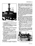
 Next
Next
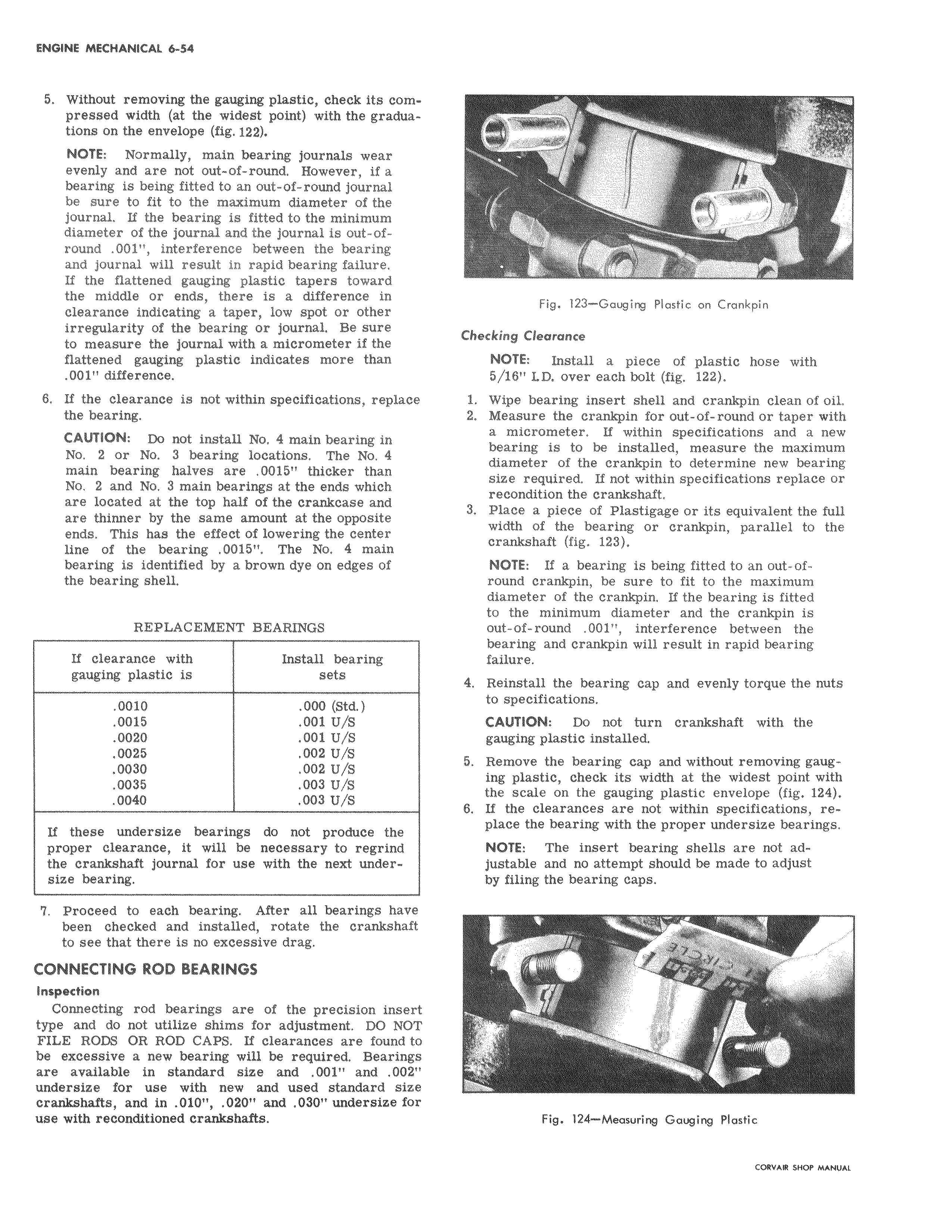
5 Without removing the gauging plastic check its com I pressed width at the widest point with the graduations on the envelope fig 122 NOTE Normally main bearing journals wear evenly and are not out of round However if a bearing is being fitted to an out of round journal be sure to fit to the maximum diameter of the journal If the bearing is fitted to the minimum diameter of the journal and the journal is out ofround 001 interference between the bearing and journal will result in rapid bearing failure If the flattened gauging plastic tapers toward the middle or ends there is a difference in clearance indicating a taPerr low spot or other irregularity of the bearing or journal Be sure to measure the journal with a micrometer if the flattened gauging plastic indicates more than 001 difference 8 If the clearance is not within specifications replace the bearing CAUTION Do not install No 4 main bearing in No 2 or No 3 bearing locations The No 4 main bearing halves are 0015 thicker than No 2 and No 3 main bearings at the ends which I are located at the top half of the crankcase and are thinner by the same amount at the opposite ends This has the effect of lowering the center line of the bearing 0015 The No 4 main bearing is identified by a brown dye on edges of the bearing shell REPLACEMENT BEARINGS If clearance with Install bearing gauging plastic is sets 0010 000 Std 0015 001 U S 0020 001 U S 0025 002 U S 0030 002 U S 0035 003 U S 0040 003 U S If these undersize bearings do not produce the proper clearance it will be necessary to regrind the crankshaft journal for use with the next undersize bearing Proceed to each bearing After all bearings have been checked and installed rotate the crankshaft to see that there is no excessive drag CONNECTING ROD BEARINGS Inspection Connecting rod bearings are of the precision inse It type and do not utilize shims for adjustment DO NO C FILE RODS OR ROD CAPS If clearances are found t be excessive a new bearing will be required Bearing are available in standard size and 001 and 002t undersize for use with new and used standard siz crankshafts and in 010 020 and 030 undersize fo use with reconditioned crankshafts I Y V J I J Fig 123 Gauging Plastic on Crankpin Checking Clearance NOTE Install a piece of plastic hose with 5 16 LD over each bolt fig 122 1 Wipe bearing insert shell and crankpin clean of oil Z Measure the crankpin for out of round or taper with a micrometer If within specifications and a new bearing is to be installed measure the maximum diameter of the crankpin to determine new bearing size required If not within specifications replace or recondition the crankshaft 3 Plade a piece of Plastigage or its equivalent the full width of the bearing or crankpin parallel to the crankshaft fig 123 NOTE If a bearing is being fitted to an out ofround Crankpin be sure to fit to the maximum diameter of the crankpin If the bearing is fitted to the minimum diameter and the crankpin is out of round 001 interference between the bearing and crankpin will result in rapid bearing failure 4 Reinstall the bearing cap and evenly torque the nuts to specifications CAUTION Do not turn crankshaft with the gauging plastic installed 5 Remove the bearing cap and without removing gauging plastic check its width at the widest point with the scale on the gauging plastic envelope fig 124 6 If the clearances are not within specifications replace the bearing with the proper undersize bearings NOTE The insert bearing shells are not adjustable and no attempt should be made to adjust by filing the bearing caps Fig 124 Measuring Gauging Plastic