Jeep Parts Wiki | Ford Parts Wiki
Home | Search | Browse
|
Corvair Chassis Shop Manual December 1964 |
|
Prev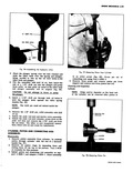
 Next
Next
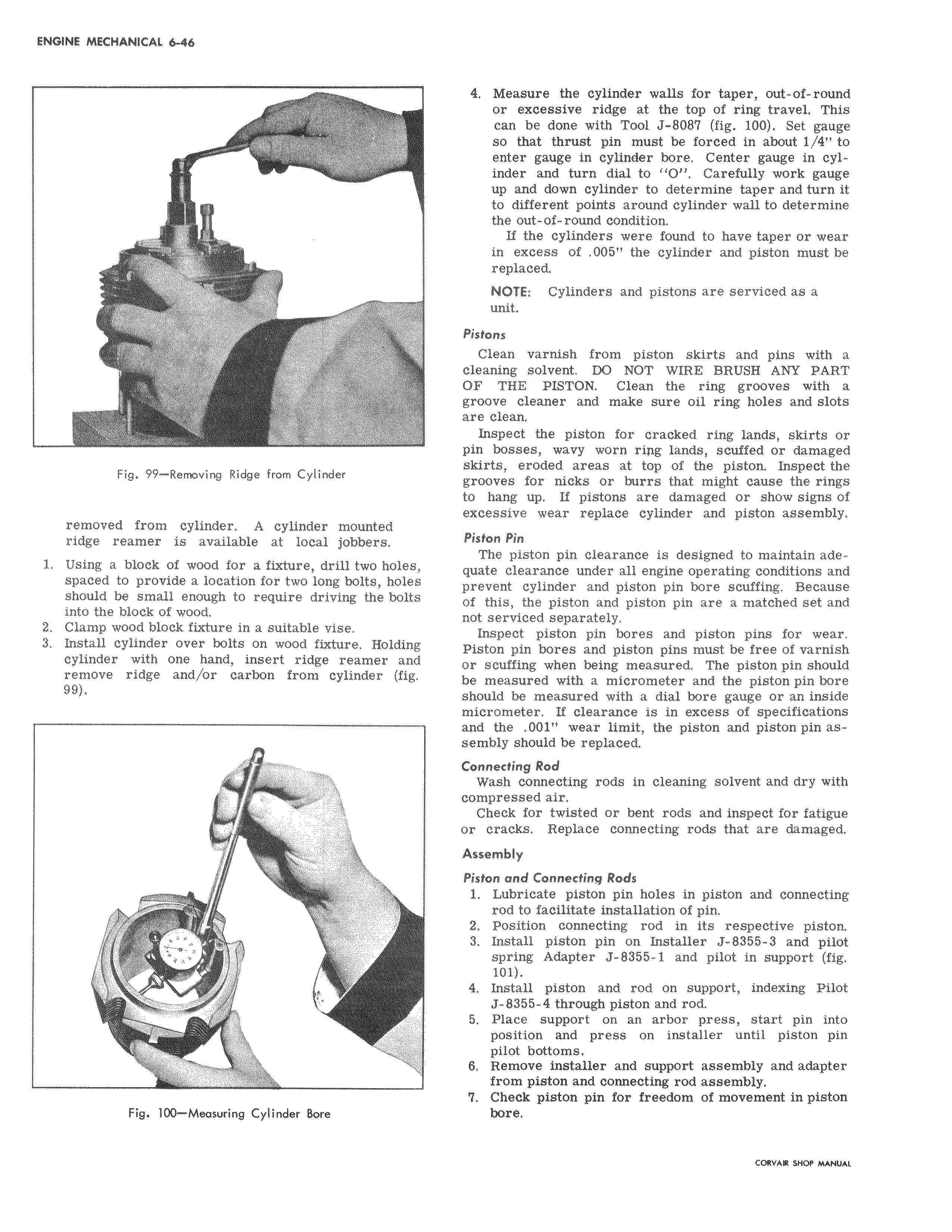
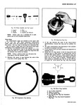
w w m o n 6 t r r F i f AF 12 4 Me ure the cylinder walls for taper out of round or xcessive ridge at the top of ring travel This can I be done with Tool J 8087 fig 100 Set gauge so hat thrust pin must be forced in about i 4 to entei gauge in cylinder bore Center gauge in cylinder and turn dial to O Carefully work gauge up and down cylinder to determine taper and turn it to different points around cylinder wall to determine the put of round condition If the cylinders were found to have taper or wear in excess of 005 the cylinder and piston must be replaced NOl6E Cylinders and pistons are serviced as a unit Pistons Clean varnish from piston skirts and pins with a cleaning solvent DO NOT WIRE BRUSH ANY PART OF THE PISTON Clean the ring grooves with a groove cleaner and make sure oil ring holes and slots are clean Inspect the piston for cracked ring lands skirts or pin bosses wavy worn ring lands scuffed or damaged skirts eroded areas at top of the piston Inspect the grooves for nicks or burrs that might cause the rings to hang up If pistons are damaged or show signs of excessive wear replace cylinder and piston assembly Piston Pin The piston pin clearance is designed to maintain adequate clearance under all engine operating conditions and prevent cylinder and piston pin bore scuffing Because of this the piston and piston pin are a matched set and not serviced separately Inspect piston pin bores and piston pins for wear Piston pin bores and piston pins must be free of varnish or scuffing when being measured The piston pin should be mea8ured with a micrometer and the piston pin bore should be measured with a dial bore gauge or an inside micromleter If clearance is in excess of specifications and the 001 wear limit the piston and piston pin assembly should be replaced Connecting Rod Wash connecting rods in cleaning solvent and dry with compressed air Check for twisted or bent rods and inspect forfatigue or cracks Replace connecting rods that are damaged Assembly Piston aind Connecting Rods 1 Lubricate piston pin holes in piston and connecting rod to facilitate installation of pin 2 Position connecting rod in its respective piston 3 Install piston pin on Installer J 8355 3 and pilot spring Adapter J 8355 1 and pilot in support fig 101 4 Indtall piston and rod on support indexing Pilot J 0355 4 through piston and rod 5 Place support on an arbor press start pin into po ition and press on installer until piston pin pilot bottoms 6 Remove installer and support assembly and adapter from piston and connecting rod assembly 7 Chbck piston gin for freedom of movement in piston bore