Jeep Parts Wiki | Ford Parts Wiki
Home | Search | Browse
|
Corvair Chassis Shop Manual December 1964 |
|
Prev
 Next
Next
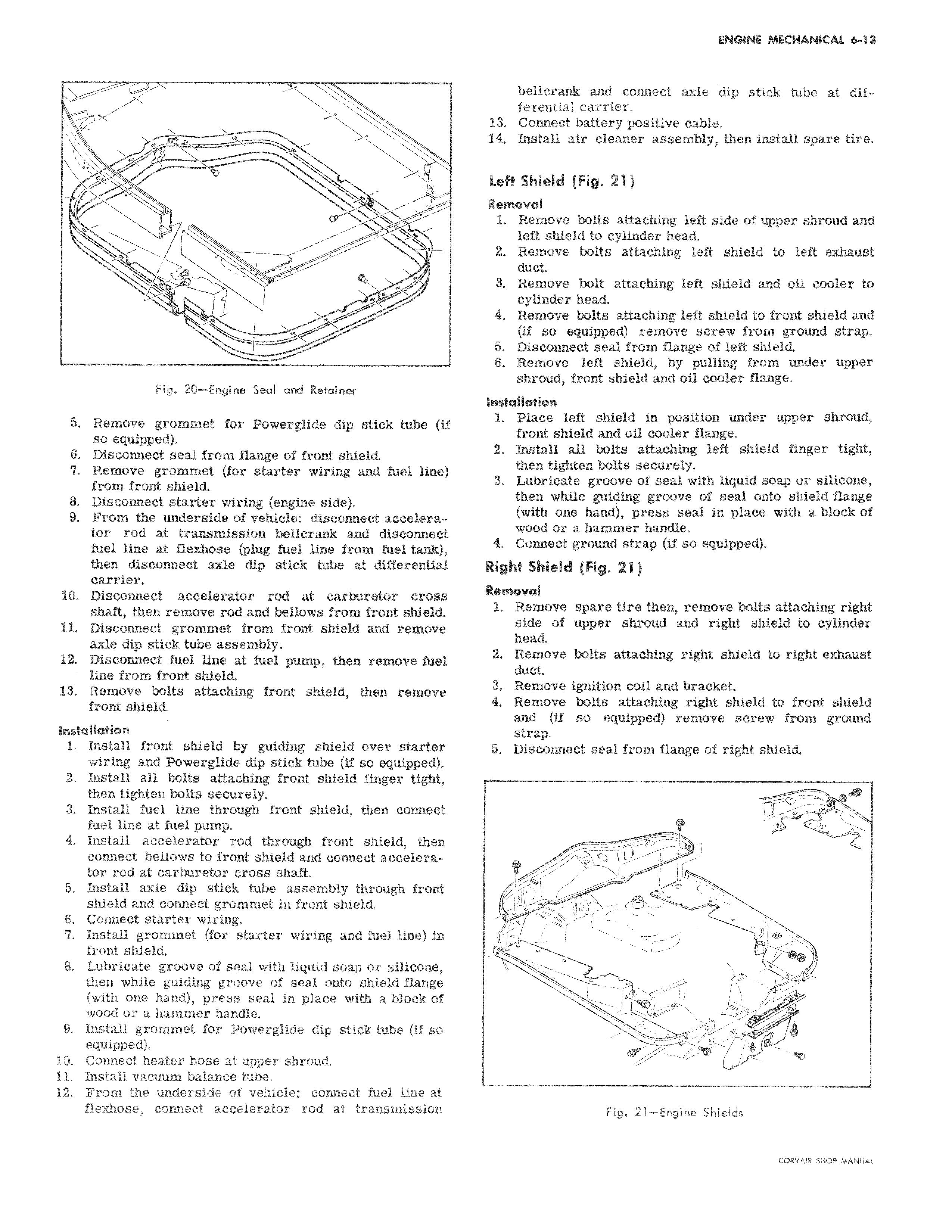
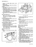
i w Fig 20 Engine Seal and Retainer 5 Remove grommet for Powerglide dip stick tube if so equipped 6 Disconnect seal from flange of front shield 7 Remove grommet for starter wiring and fuel line from front shield 8 Disconnect starter wiring engine side 9 From the underside of vehicle disconnect accelerator rod at transmission bellcrank and disconnect fuel line at fleahose plug fuel line from fuel tank then disconnect axle dip stick tube at differential carrier 10 Disconnect accelerator rod at carburetor cross shaft then remove rod and bellows from front shield 11 Disconnect grommet from front shield and remove axle dip stick tube assembly 12 Disconnect fuel line at fuel pump then remove fuel line from front shield 13 Remove bolts attaching front shield then remove front shield Installation 1 Install front shield by guiding shield over starter wiring and Powerglide dip stick tube if so equipped 2 Install all bolts attaching front shield finger tight then tighten bolts securely 3 Install fuel line through front shield then connect fuel line at fuel pump 4 Install accelerator rod through front shield then connect bellows to front shield and connect accelerator rod at carburetor cross shaft 5 Install axle dip stick tube assembly through front shield and connect grommet in front shield 6 Connect starter wiring 7 Install grommet for starter wiring and fuel line in front shield 8 Lubricate groove of seal with liquid soap or silicone then while guiding groove of seal onto shield flange with one hand press seal in place with a block of wood or a hammer handle 9 Install grommet for Powerglide dip stick tube if so equipped 10 Connect heater hose at upper shroud 11 Install vacuum balance tube 12 From the underside of vehicle connect fuel line at flexhose connect accelerator rod at transmission bellcrank and connect axle dip stick tube at differential carrier 13 Connect battery positive cable 14 Install air cleaner assembly then install spare tire Left Shield Fig 21 j Removal 1 Remove bolts attaching left side of upper shroud and left shield to cylinder head 2 Remove bolts attaching left shield to left exhaust duct 3 Remove bolt attaching left shield and oil cooler to cylinder head 4 Remove bolts attaching left shield to front shield and if so equipped remove screw from ground strap 5 Disconnect seal from flange of left shield 6 Remove left shield by pulling from under upper shroud front shield and oil cooler flange Installation 1 Place left shield in position under upper shroud front shield and oil cooler flange 2 Install all bolts attaching left shield finger tight then tighten bolts securely 3 Lubricate groove of seal with liquid soap or silicone then while guiding groove of seal onto shield flange with one hand press seal in place with a block of wood or a hammer handle 4 Connect ground strap if so equipped Right Shield Fig 21 Removal 1 Remove spare tire then remove bolts attaching right side of upper shroud and right shield to cylinder head 2 Remove bolts attaching right shield to right exhaust duct 3 Remove ignition coil and bracket 4 Remove bolts attaching right shield to front shield and if so equipped remove screw from ground strap 5 Disconnect seal from flange of right shield O y Fig 21 Engine Shields C 1QV IQ fXfM Y Alll 1