Jeep Parts Wiki | Ford Parts Wiki
Home | Search | Browse
|
Corvair Chassis Shop Manual December 1964 |
|
Prev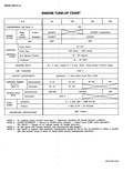
 Next
Next
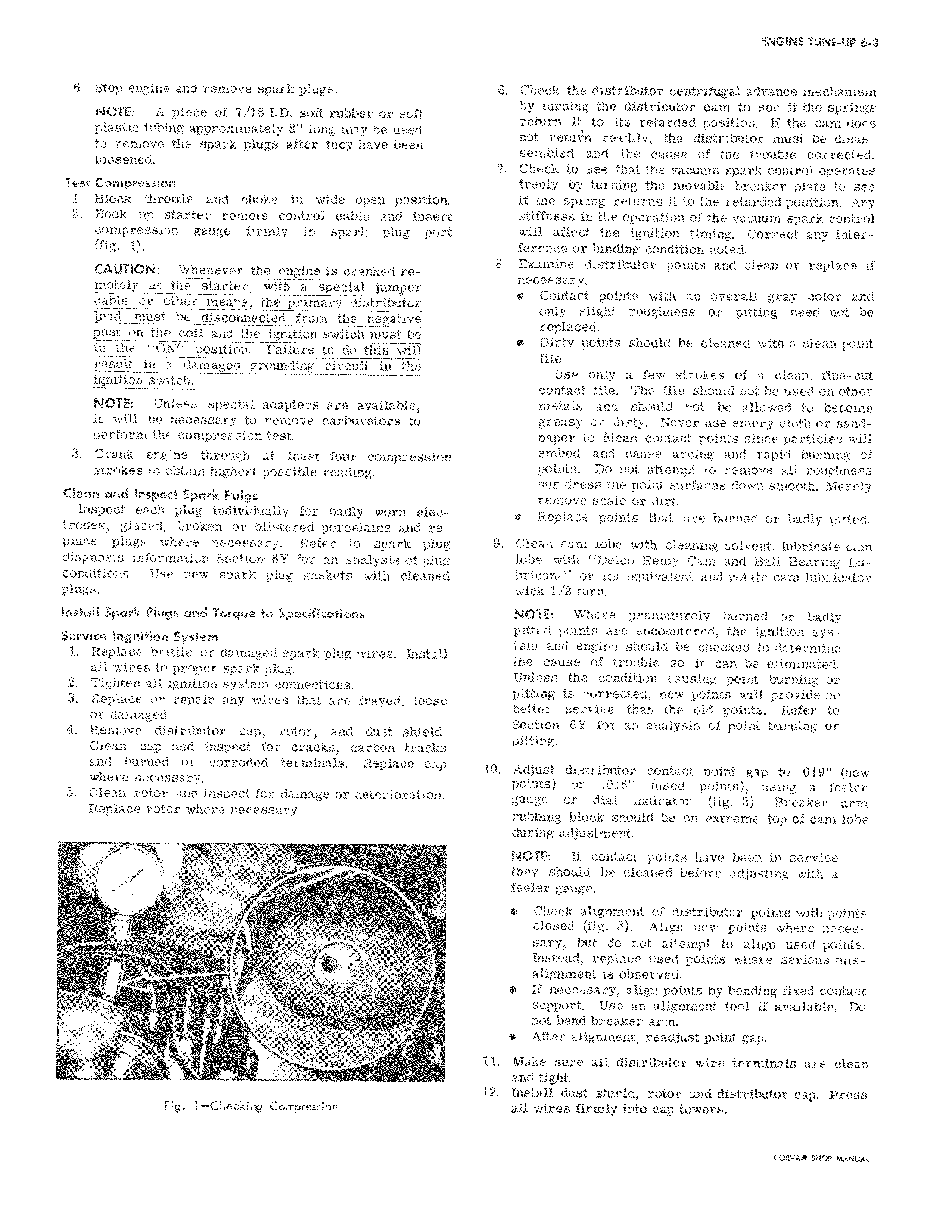
6 Stop engine and remove spark plugs NOTE A piece of 7 i6 LD soft rubber or soft plastic tubing approximately 8 long may be used to remove the spark plugs after they have been loosened Test Compression 1 Block throttle and choke in wide open position 2 Hook up starter remote control cable and insert compression gauge firmly in spark plug port fig 1 CAUTION Whenever the engine is cranked remotely at the starter with a special jumper cable or other means the primary distributor 11ead must be disconnected from the negative post on the coil and the ignition switch must be m the ON position Failure to do this will result in a damaged grounding circuit in the ignition switch NOTE Unless special adapters are available it will be necessary to remove carburetors to perform the compression test 3 Crank engine through at least four compression strokes to obtain highest possible reading Clean and Inspect Spark Pulgs Inspect each plug individually for badly worn electrodes glazed broken or blistered porcelains and replace plugs where necessary Refer to spark plug diagnosis information Sectioir 6Y for an analysis of plug conditions Use new spark plug gaskets with cleaned plugs Install Spark Plugs and Torque to Specifications Service Ingnition System 1 Replace brittle or damaged spark plug wires Install all wires to proper spark plug 2 Tighten all ignition system connections 3 Replace or repair any wires that are frayed loose or damaged 4 Remove distributor cap rotor and dust shield Clean cap and inspect for cracks carbon tracks and burned or corroded terminals Replace cap where necessary 5 Clean rotor and inspect for damage or deterioration Replace rotor where necessary t r Fig 1 Checking Compression 6 Check the distributor centrifugal advance mechanism by turning the distributor cam to see if the springs return it to its retarded position If the cam does not retur n readily the distributor must be disassembled and the cause of the trouble corrected 7 Check to see that the vacuum spark control operates freely by turning the movable breaker plate to see if the spring returns it to the retarded position Any stiffness in the operation of the vacuum spark control will affect the ignition timing Correct any interference or binding condition noted 8 Examine distributor points and clean or replace if necessary Contact points with an overall gray color and only slight roughness or pitting need not be replaced Dirty points should be cleaned with a clean point file Use only a few strokes of a clean fine cut contact file The file should not be used on other metals and should not be allowed to become greasy or dirty Never use emery cloth or sandpaper to i lean contact points since particles will embed and cause arcing and rapid burning of points Do not attempt to remove all roughness nor dress the point surfaces down smooth Merely remove scale or dirt Replace points that are burned or badly pitted 9 Clean cam lobe with cleaning solvent lubricate cam lobe with Delco Remy Cam and Ball Bearing Lubricant or its equivalent and rotate cam lubricator wick 1 2 turn NOTE Where prematurely burned or badly pitted points are encountered the ignition system and engine should be checked to determine the cause of trouble so it can be eliminated Unless the condition causing point burning or pitting is corrected new points will provide no better service than the old points Refer to Section 6Y for an analysis of point burning or pitting 10 Adjust distributor contact point gap to 019 new points or 016 used points using a feeler gauge or dial indicator fig 2 Breaker arm rubbing block should be on extreme top of cam lobe during adjustment NOTE If contact points have been in service they should be cleaned before adjusting with a feeler gauge Check alignment of distributor points with points closed fig 3 Align new points where necessary but do not attempt to align used points Instead replace used points where serious misalignment is observed If necessary align points by bending fixed contact support Use an alignment tool if available Do not bend breaker arm After alignment readjust point gap 11 Make sure all distributor wire terminals are clean and tight 12 Install dust shield rotor and distributor cap Press all wires firmly into cap towers CORVAR SHOP MANUAL