Jeep Parts Wiki | Ford Parts Wiki
Home | Search | Browse
|
Corvair Chassis Shop Manual December 1964 |
|
Prev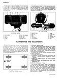
 Next
Next
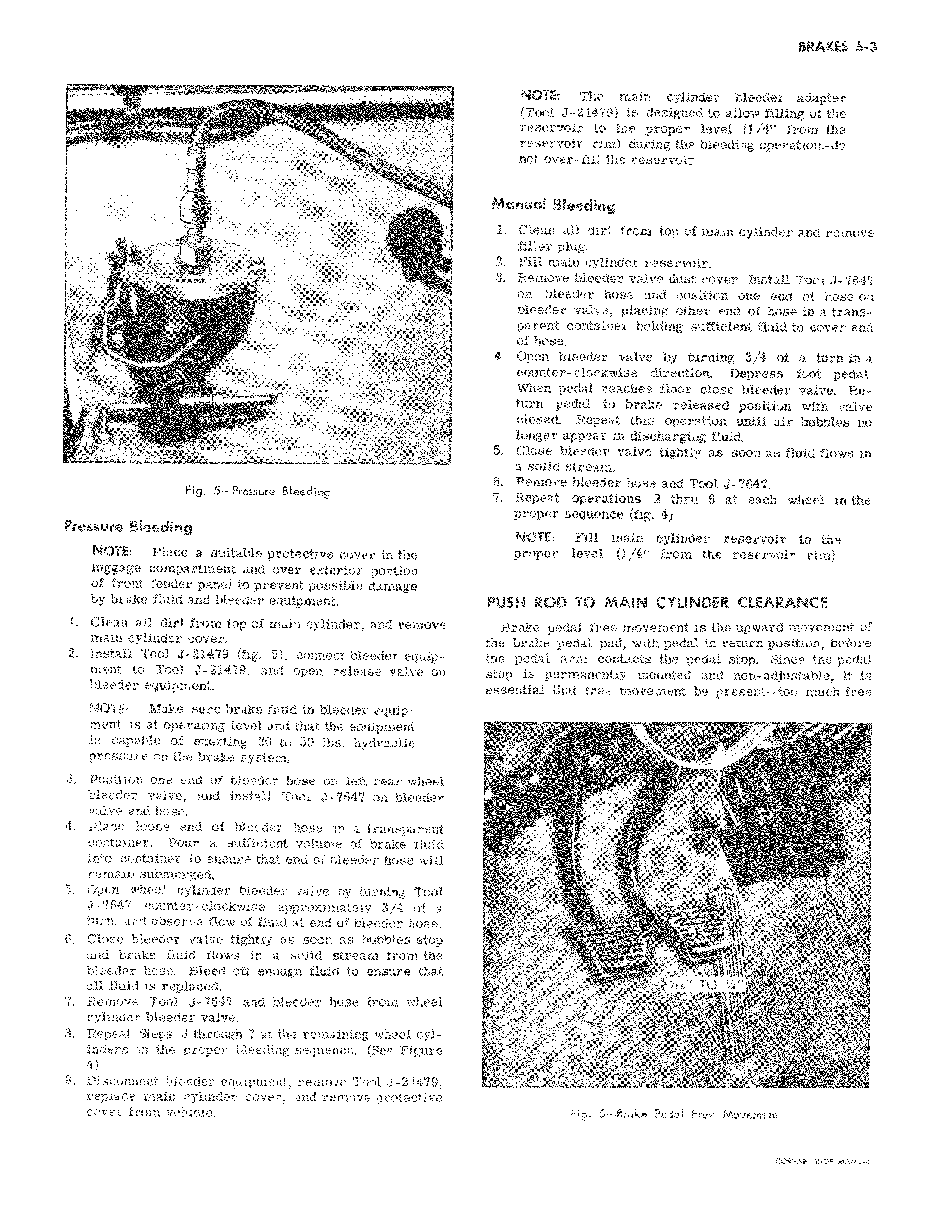
a i r 4 i Fig 5 Pressure Bleeding Pressure Bleeding NOTE Place a suitable protective cover in the luggage compartment and over exterior portion of front fender panel to prevent possible damage by brake fluid and bleeder equipment 1 Clean all dirt from top of main cylinder and remove main cylinder cover 2 Install Tool J 21479 fig 5 connect bleeder equipment to Tool J 21479 and open release valve on bleeder equipment NOTE Make sure brake fluid in bleeder equipment is at operating level and that the equipment is capable of exerting 30 to 50 lbs hydraulic pressure on the brake system 3 Position one end of bleeder hose on left rear wheel bleeder valve and install Tool J 7647 on bleeder valve and hose 4 Place loose end of bleeder hose in a transparent container Pour a sufficient volume of brake fluid into container to ensure that end of bleeder hose will remain submerged 5 Open wheel cylinder bleeder valve by turning Tool J 7647 counter clockwise approximately 3 4 of a turn and observe flow of fluid at end of bleeder hose 6 Close bleeder valve tightly as soon as bubbles stop and brake fluid flows in a solid stream from the bleeder hose Bleed off enough fluid to ensure that all fluid is replaced 7 Remove Tool J 7647 and bleeder hose from wheel cylinder bleeder valve 8 Repeat Steps 3 through 7 at the remaining wheel cylinders in the proper bleeding sequence See Figure 4 9 Disconnect bleeder equipment remove Tool J 21479 replace main cylinder cover and remove protective cover from vehicle NOTE The main cylinder bleeder adapter Tool J 21479 is designed to allow filling of the reservoir to the proper level 1 4 from the reservoir rim during the bleeding operation do not over fill the reservoir Manual Bleeding 1 Clean all dirt from top of main cylinder and remove filler plug 2 Fill main cylinder reservoir 3 Remove bleeder valve dust cover Install Tool J 647 on bleeder hose and position one end of hose on bleeder val a placing other end of hose in a transparent container holding sufficient fluid to cover end of hose 4 Open bleeder valve by turning 3 4 of a turn in a counter clockwise direction Depress foot pedal When pedal reaches floor close bleeder valve Return pedal to brake released position with valve closed Repeat this operation until air bubbles no longer appear in discharging fluid 5 Close bleeder valve tightly as soon as fluid flows in a solid stream 6 Remove bleeder hose and Tool J 7647 7 Repeat operations 2 thru 6 at each wheel in the proper sequence fig 4 NOTE Fill main cylinder reservoir to the proper level 1 4 from the reservoir rim PUSH ROD TO MAIN CYLINDER CLEARANCE Brake pedal free movement is the upward movement of the brake pedal pad with pedal in return position before the pedal arm contacts the pedal stop Since the pedal stop is permanently mounted and non adjustable it is essential that free movement be present too much free S r x r I 2 1 16 TO a Fig 6 Brake Pedal Free Nbvement rrov o curo www