Jeep Parts Wiki | Ford Parts Wiki
Home | Search | Browse
|
Corvair Chassis Shop Manual December 1964 |
|
Prev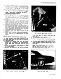
 Next
Next
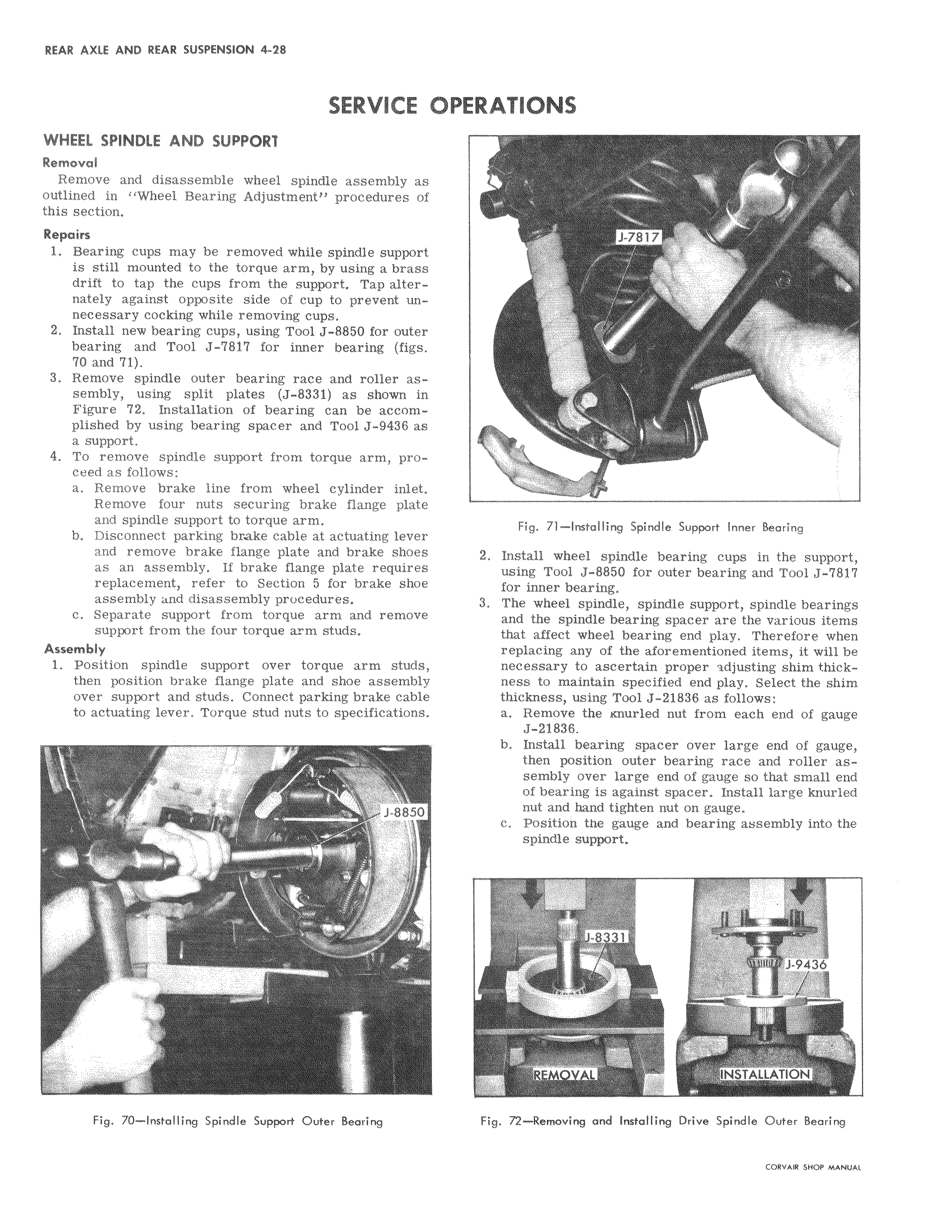
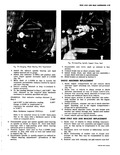
SERVICE I OI WHEEL SPINDLE AND SUPPORt Removal Remove and disassemble wheel spindle assembly al outlined in Wheel Bearing Adjustment procedures f this section Repairs 1 Bearing cups may be removed while spindle support is still mounted to the torque arm by using a bras s drift to tap the cups from the support Tap aiter nately against opposite side of cup to prevent unlr necessary cocking while removing cups 2 Install new bearing cups using Tool J 8850 for outer bearing and Tool J 7817 for inner bearing fig 70 and 71 3 Remove spindle outer bearing race and roller assembly using split plates J 8331 as shown i n Figure 72 Installation of bearing can be acc o plished by using bearing spacer and Tool J 9436 s a support 4 To remove spindle support from torque arm pr ceed as follows a Remove brake line from wheel cylinder inlet Remove four nuts securing brake flange plate and spindle support to torque arm b Disconnect parking brake cable at actuating lever and remove brake flange plate and brake shoes as an assembly If brake flange plate requir s replacement refer to Section 5 for brake se assembly and disassembly procedures c Separate support from torque arm and remo4e support from the four torque a m studs Assembly 1 Position spindle support over torque arm studLs then position brake flange plate and shoe assemb y over support and studs Connect parking brake cab e to actuating lever Torque stud nuts to specifications J 88 Fig 70 Installing Spindle Support Outer Bearing IERATIONS J 7817 i i Fig 71 Installing Spindle Support Inner Bearing 2 Install wheel spindle bearing cups in the support using Tool J 8850 for outer bearing and Tool J 7817 for inner bearing 3 The wheel spindle spindle support spindle bearings and the spindle bearing spacer are the various items that affect wheel bearing end play Therefore when replacing any of the aforementioned items it will be necessary to ascertain proper djusting shim thickness to maintain specified end play Select the shim thickness using Tool J 21836 as follows a Remove the Knurled nut from each end of gauge J 21836 b Install bearing spacer over large end of gauge then position outer bearing race and roller assembly over large end of gauge so that small end of bearing is against spacer Install large knurled nut and hand tighten nut on gauge c j Position the gauge and bearing assembly into the spindle support J 9436 i N ILLATION Fig 72 Removing and Installing Drive Spindle Outer Bearing