Jeep Parts Wiki | Ford Parts Wiki
Home | Search | Browse
|
Corvair Chassis Shop Manual December 1964 |
|
Prev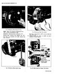
 Next
Next
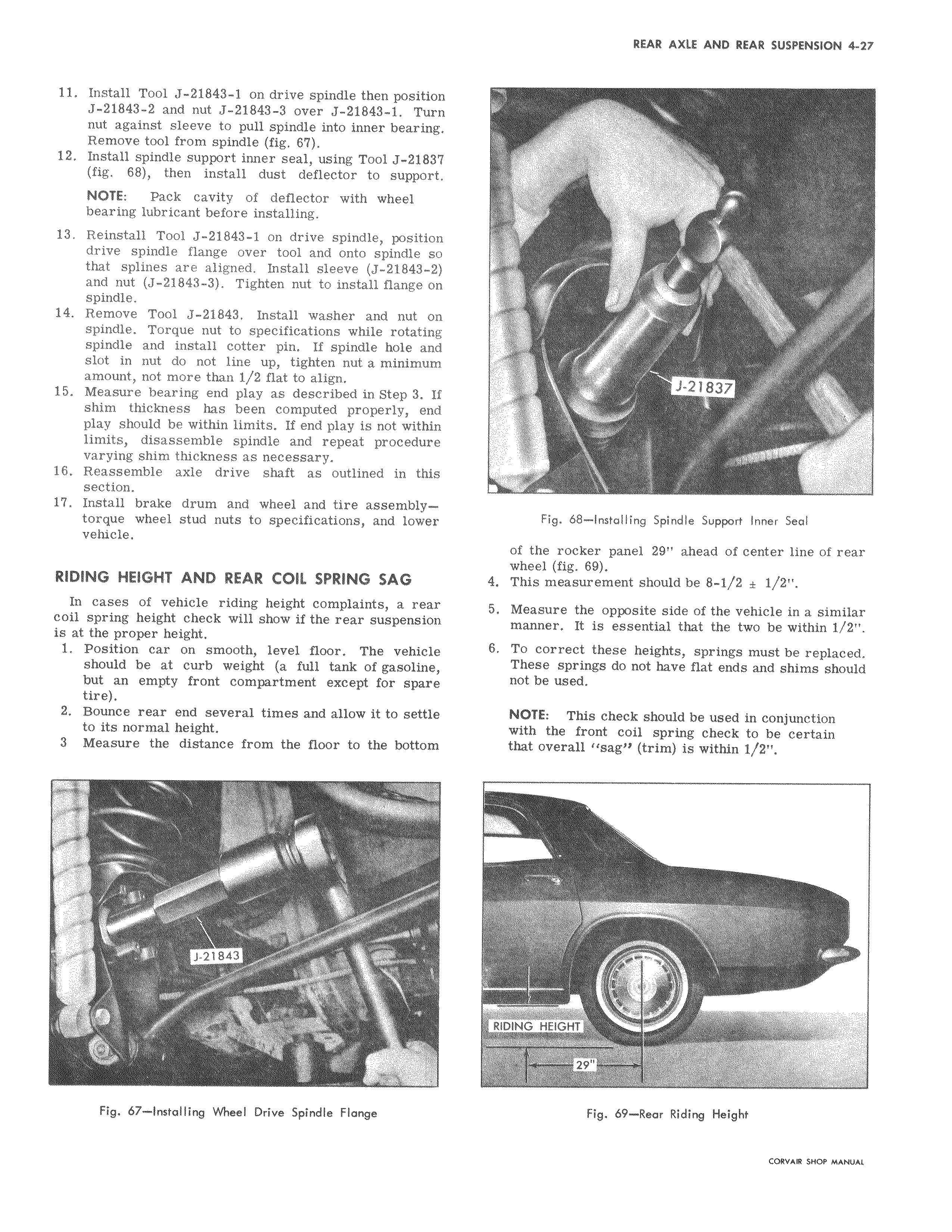
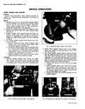
11 Install Tool J 21843 1 on drive spindle then position J 21843 2 and nut J 21843 3 over J 21843 1 Turn nut against sleeve to pull spindle into inner bearing Remove tool from spindle fig 67 12 Install spindle support inner seal using Tool J 21837 fig 68 then install dust deflector to support NOTE Pack cavity of deflector with wheel bearing lubricant before installing 13 Reinstall Tool J 21843 1 on drive spindle position drive spindle flange over tool and onto spindle so that splines are aligned Install sleeve J 21843 2 and nut J 21843 3 Tighten nut to install flange on spindle 14 Remove Tool J 21843 Install washer and nut on spindle Torque nut to specifications while rotating spindle and install cotter pin If spindle hole and slot in nut do not line up tighten nut a minimum amount not more than 1 2 flat to align 15 Measure bearing end play as described in Step 3 If shim thickness has been computed properly end play should be within limits If end play is not within limits disassemble spindle and repeat procedure varying shim thickness as necessary 16 Reassemble axle drive shaft as outlined in this section 17 Install brake drum and wheel and tire assemblytorque wheel stud nuts to specifications and lower vehicle RIDING HEIGHT AND REAR COIL SPRING SAG In cases of vehicle riding height complaints a rear coil spring height check will show if the rear suspension is at the proper height 1 Position car on smooth level floor The vehicle should be at curb weight a full tank of gasoline but an empty front compartment except for spare tire 2 Bounce rear end several times and allow it to settle to its normal height 3 Measure the distance from the floor to the bottom 47 1 aiq J 21843 Y Fig 67 Installing Wheel Drive Spindle Flange r r r t Y J 21837 r Fig 68 Installing Spindle Support Inner Seal of the rocker panel 29 ahead of center line of rear wheel fig 69 4 This measurement should be 8 1 2 f 1 2 5 Measure the opposite side of the vehicle in a similar manner It is essential that the two be within 1 2 6 To correct these heights springs must be replaced These springs do not have flat ends and shims should not be used NOTE This check should be used in conjunction with the front coil spring check to be certain that overall sag trim is within 1 2 RIDING HEIGHCT s 29 Fig 69 Rear Riding Height CORVAR SHOP MANUAL