Jeep Parts Wiki | Ford Parts Wiki
Home | Search | Browse
|
Corvair Chassis Shop Manual December 1964 |
|
Prev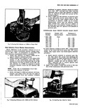
 Next
Next
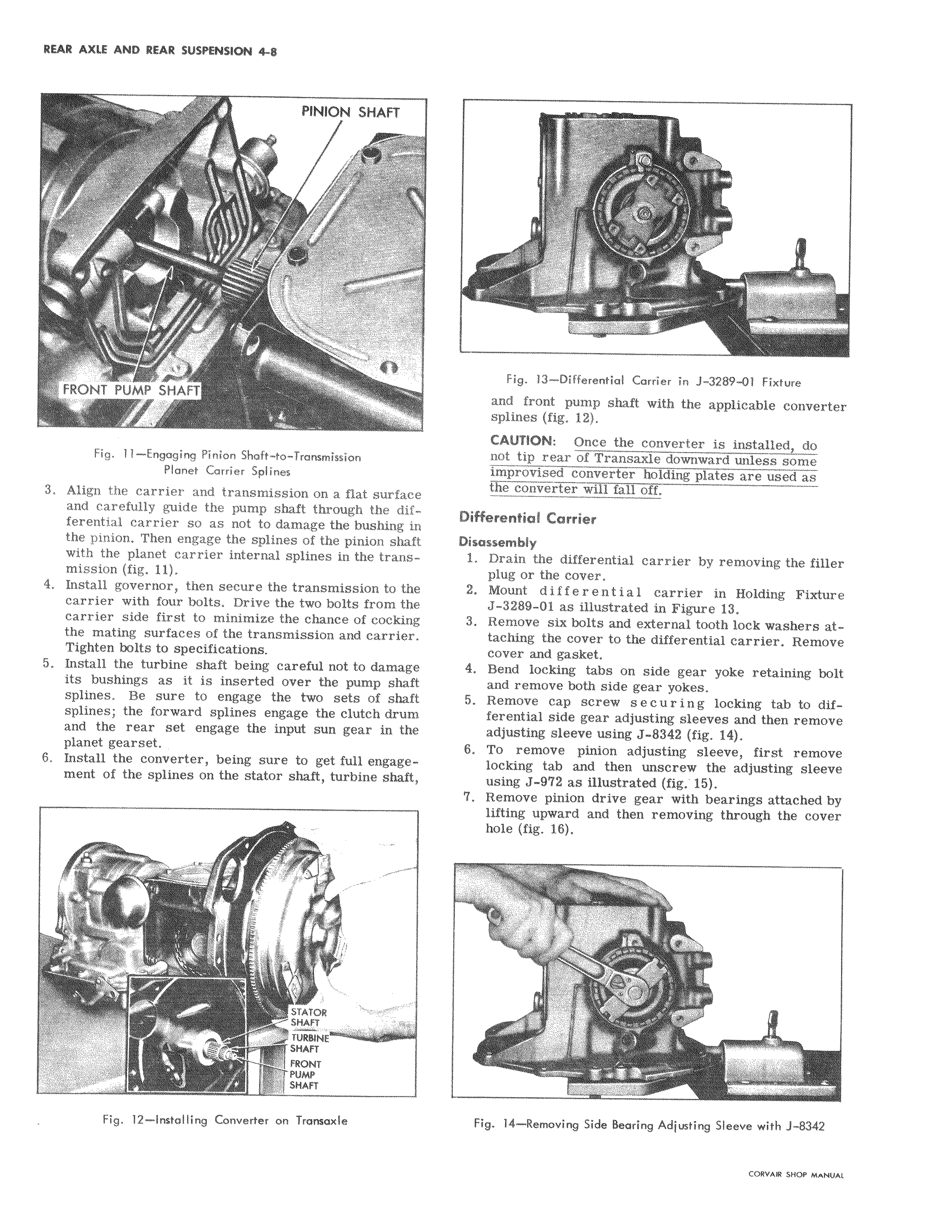
PINION SHAFT r FRONT PUMP SHAFT Fig 11 Engaging Pinion Shaft to Transmission Planet Carrier Splines I 3 Align the carrier and transmission on a flat surface and carefully guide the pump shaft through the dif ferential carrier so as not to damage the bushing m the pinion Then engage the splines of the pinion shaft with the planet carrier internal splines in the transmission fig 11 4 Install governor then secure the transmission to the carrier with four bolts Drive the two bolts from the carrier side first to minimize the chance of cocking the mating surfaces of the transmission and carrier Tighten bolts to specifications 5 Install the turbine shaft being careful not to damage its bushings as it is inserted over the pump shaft splines Be sure to engage the two sets of shaft splines the forward splines engage the clutch drum and the rear set engage the input sun gear in the planet gearset 6 Install the converter being sure to get full engage4 ment of the splines on the stator shaft turbine shafti t STATOR I SkAFT TURN SHAFT FRONT SHAFT Fig 12 Installing Converter on Transaxle I i a i NO 13 Differential Carrier in J 3289 01 Fixture and h front pump shaft with the applicable converter splines fig 12 i CAUTION Once the converter is installed do not iip rear of Transaxle downward unless some imptovised converter holding plates are used as e Converter will fall off Differenlfial Carrier Disassembly 1 Drain the differential carrier by removing the filler plug or the cover 2 Mouht differential carrier in Holding Fixture J 3289 O1 as illustrated in Figure 13 3 Remove six bolts and external tooth lock washers attaching the cover to the differential carrier Remove cover and gasket 4 BerA locking tabs on side gear yoke retaining bolt and remove both side gear yokes 5 Remove cap screw s e c u r i n g locking tab to differential side gear adjusting sleeves and then remove adjusting sleeve using J 8342 fig 14 6 To remove pinion adjusting sleeve first remove locking tab and then unscrew the adjusting sleeve using J 972 as illustrated fig 15 7 Remove pinion drive gear with bearings attached by lifting upward and then removing through the cover hole fig 16 G S k A I T FIL Fig 14 Removing Side Bearing Adjusting Sleeve with J 8342