Jeep Parts Wiki | Ford Parts Wiki
Home | Search | Browse
|
Corvair Chassis Shop Manual December 1964 |
|
Prev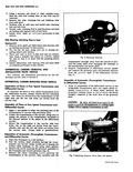

 Next
Next
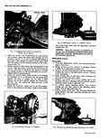
Fig 8 Zeroing Dial Indicator on J 8364 on Output Shaft Rear Selective Thrust Washer Determination Strict adherence to the procedure outlined below is mandatory to insure Powerglide internal running clearance of 025 045 If transmission is assembled with less clearance transmission failure is probable a Install dial indicator on Support J 8364 and install 3 indicator extension provided b Without gasket place support on rear pump cavity surface of the transmission case with transmission on front end as illustrated fig 8 so that dial indicator tip rests on planet carrier hub Adjust indicator on J 8364 as required to permit maximum indicator travel and set indicator dial to zero NOTE Front end of transmission must face downward when indicator is zeroed c Slowly lift Support J 8364 and indicator off transmission rear pump cavity and note its range of needle deflection from zero position Properly positioned on support indicator should not deflect more than 050 one half turn when removed otherwise raise or lower dial indicator on support post as required and again zero gauge as described in Step b d Place J 8364 and dial indicator on governor gear on the differential carrier pinion shaft as illustrated fig 9 and lower support slowly so that revolutions of indicator needle can be counted Measurement starts once the indicator needle again reaches zero Fully d e p r e s s support on governor gear note indicator reading and refer to the following chart for spacers to be installed on governor gear POWERGLIDE REAR THRUST SPACER USAGE CHART Indicator Number 016 Thickness of Reading Spacers Req d Spacers Installed 025 046 None 047 062 1 016 t 001 063 078 2 032 t 002 079 094 3 048 f 003 095 110 4 064 t 004 111 126 5 080 f 005 127 142 6 096 t 006 143 155 7 112 f 007 If initial indicator reading is below 025 replace thrust washer at the clutch hub front pump with 050 thrust washer then repeat entire rear thrust spacer selection procedure e Install spacers selected on governor gear fig 10 then check that proper total thickness has been installed by again measuring with J 8364 as described in Step d If shim stack is correct indicator reading will now be between 025 045 otherwise add or remove spacers until reading is within this range 2 Apply a new gasket to either the carrier or the rear face of the transmission with petroleum jelly