Jeep Parts Wiki | Ford Parts Wiki
Home | Search | Browse | Marketplace | Messages | FAQ | Guest
|
Corvair Chassis Shop Manual December 1964 |
|
Prev
 Next
Next
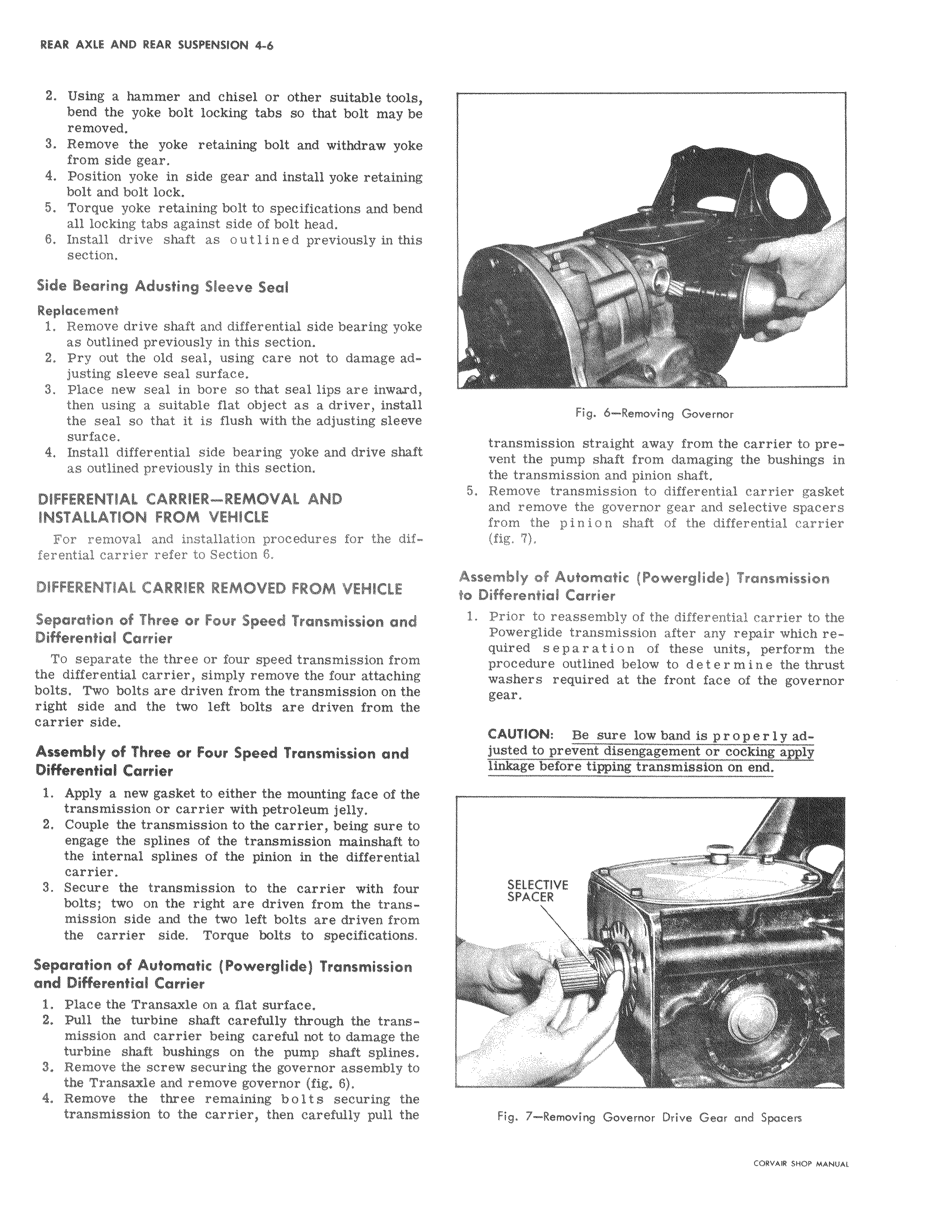
2 Using a hammer and chisel or other suitable tools i bend the yoke bolt locking tabs so that bolt may be removed 3 Remove the yoke retaining bolt and withdraw yoke I from side gear 4 Position yoke in side gear and install yoke retaining bolt and bolt lock 5 Torque yoke retaining bolt to specifications and bendi all locking tabs against side of bolt head 8 Install drive shaft as outlined previously in thisi section Side Bearing Adusting Sleeve Seal I Replacement 1 Remove drive shaft and differential side bearing yoke as Outlined previously in this section I 2 Pry out the old seal using care not to damage ad I justing sleeve seal surface I 3 Place new seal in bore so that seal lips are inward then using a suitable flat object as a driver instali the seal so that it is flush with the adjusting sleev surface 4 Install differential side bearing yoke and drive shaft as outlined previously in this section DIFFERENTIAL CARRIER REMOVAL AND INSTALLATION FROM VEHICLE I For removal and installation procedures for the dif7 ferential carrier refer to Section 6 DIFFERENTIAL CARRIER REMOVED FROM VEHICLE I Separation of Three or Four Speed Transmission and l Differential Carrier I To separate the three or four speed transmission from the differential carrier simply remove the four attaching bolts Two bolts are driven from the transmission on the right side and the two left bolts are driven from the carrier side Assembly of Three or Four Speed Transmission and II Differential Carrier 1 Apply a new gasket to either the mounting face of the transmission or carrier with petroleum jelly 2 Couple the transmission to the carrier being sure to engage the splines of the transmission mainshaft to the internal splines of the pinion in the differential carrier I 3 Secure the transmission to the carrier with fou bolts two on the right are driven from the trans mission side and the two left bolts are driven fro p the carrier side Torque bolts to specific s Separation of Automatic Powerglide Transmissionl and Differential Carrier 1 Place the Transaxle on a flat surface 2 Pull the turbine shaft carefully through the translmission and carrier being careful not to damage the turbine shaft bushings on the pump shaft splines 3 Remove the screw securing the governor assembly to the Transaxle and remove governor fig 6 4 Remove the three remaining bolts securing th transmission to the carrier then carefully pull thle I w 711 00 a