Jeep Parts Wiki | Ford Parts Wiki
Home | Search | Browse | Marketplace | Messages | FAQ | Guest
|
Corvair Chassis Shop Manual December 1964 |
|
Prev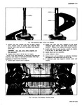

 Next
Next
FRONT SUSPENSION CROSSMEMBER This crossmember may be removed as either a complete front suspension system including wheels andi brake assemblies or after all components have been removed The basic crossmember removal and installation procedures are the same in either case Individual item removal and installation bench overhaul on a complete front suspension are handled in a similar I manner as outlined under the respective headings for i each component One notable exception being spring removal This may be handled by using large 1 C clamps or other suitable means for compressing and slowly lessening coil spring tension Removal 1 Raise vehicle on hoist or jack stands and support so the front suspension will swing free 2 Remove both brake pipes from the brake hoses and remove the hoses from the body brackets 3 Remove the speedometer cable bracket attaching bolts and withdraw cable from spindle 4 Remove the two cotter keys and nuts that securel the outer ends of the tie rods to the steering arms 5 Place the front post of a hoist or other means to allow lowering and raising of crossmember under I I the Crossmember and remove the six bolts three eachi side that attach the crossmember to the frame fig 3 24 One of the three bolts per each side is actually up through the strut rod bracket NOTE Care and caution must be used to restrain erossmember and see that it does not fall or slip from its support 6 Lower crossmember to floor Installation 1 Raise crossmember into position Align the bolt holes with a tapered punch and install the six bolts Do not tighten any one bolt until all six are in place or alignment may become difficult Tighten attaching bolts 2 Lower post of hoist if used or withdraw lifting device 3 Instill the tie rod studs into the steering arm and properly install nuts and cotter keys 4 Instill the brake hoses to the body brackets and instill the brake pipes to the hoses Be certain to bleed the brakes and position the hoses as outlined in Section 5 Brakes 5 Instill the speedometer cable and attaching bracket 6 Lowier vehicle to floor i i