Jeep Parts Wiki | Ford Parts Wiki
Home | Search | Browse
|
Corvair Chassis Shop Manual December 1964 |
|
Prev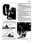
 Next
Next
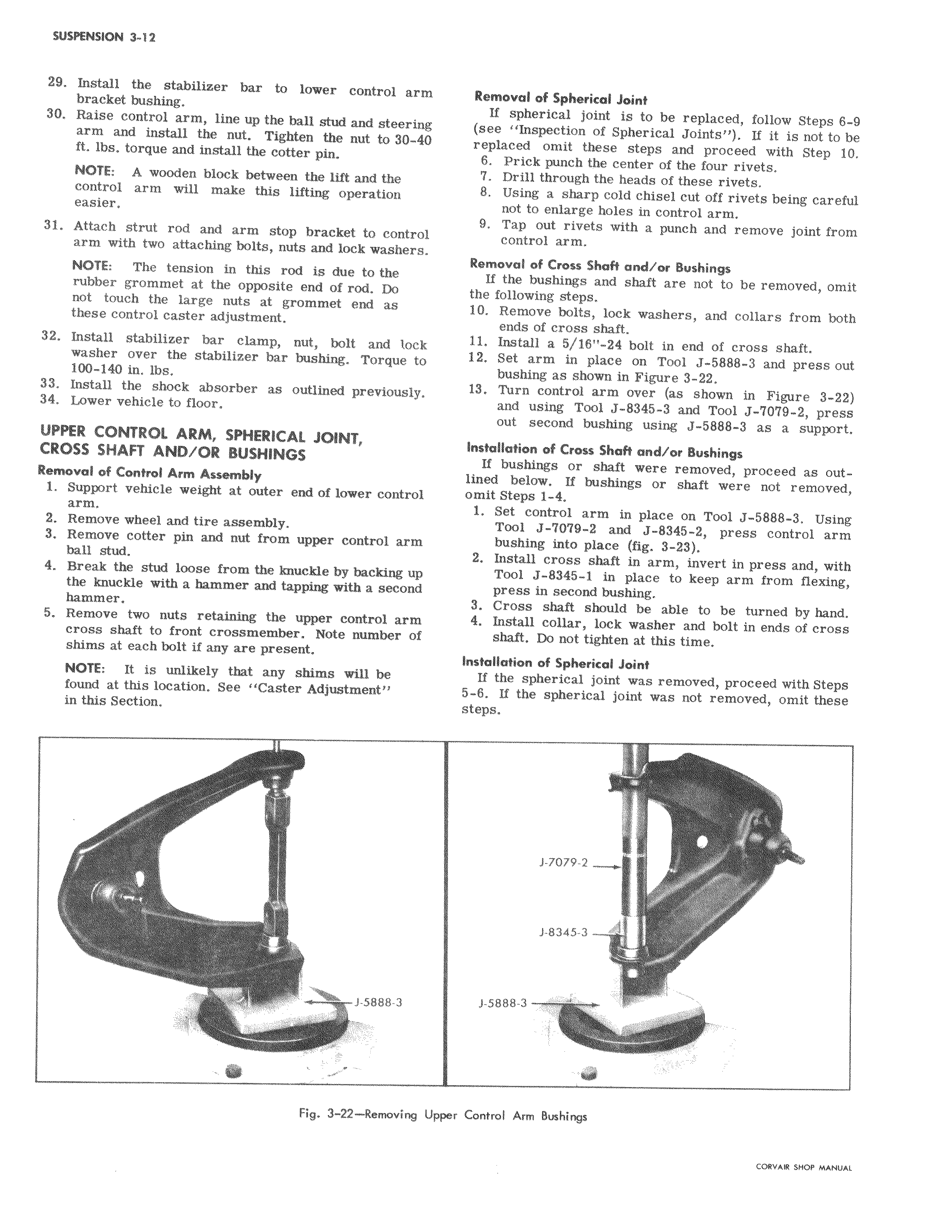
29 Install the stabilizer bar to lower control arm bracket bushing 30 Raise control arm line up the ball stud and steerinlg arm and install the nut Tighten the nut to 30 4 0 ft lbs torque and install the cotter pin I NOTE A wooden block between the lift and the control arm will make this lifting operation easier 31 Attach strut rod and arm stop bracket to contr Il arm with two attaching bolts nuts and lock washer NOTE The tension in this rod is due to the i rubber grommet at the opposite end of rod Do not touch the large nuts at grommet end as i these control caster adjustment 32 Install stabilizer bar clamp nut bolt and lock washer over the stabilizer bar bushing Torque to 100 140 in lbs 33 Install the shock absorber as outlined previously 34 Lower vehicle to floor UPPER CONTROL ARM SPHERICAL JOINT CROSS SHAFT AND OR BUSHINGS Removal of Control Ann Assembl r 1 Support vehicle weight at outer end of lower contro arm 2 Remove wheel and tire assembly 3 Remove cotter pin and nut from upper control arm ball stud 4 Break the stud loose from the knuckle by backing the knuckle with a hammer and tapping with a second hammer 5 Remove two nuts retaining the upper control arm cross shaft to front crossmember Note number o shims at each bolt if any are present NOTE It is unlikely that any shims will be found at this location See Caster Adjustment i in this Section I I J 5888 3 I r v Fig 3 22 Removini UpF I Removol of Spherical Joint If spherical joint is to be replaced follow Steps 6 9 see Inspection of Spherical Joints If it is not to be replaced omit these steps and proceed with Step 10 6 Prick punch the center of the four rivets 7 Drill through the heads of these rivets 8 Using a sharp cold chisel cut off rivets being careful not to enlarge holes in control arm 9 Tap out rivets with a punch and remove joint from co troi arm Removo of Cross Shaft and or Bushings If th4 bushings and shaft are not to be removed omit the following steps 10 Retnove bolts lock washers and collars from both e of cross shaft 11 Insn all a 5 18 24 bolt in end of cross shaft 12 Se arm in place an Tool J 5888 3 and press out as shown in Figure 3 22 13 Tu control arm over as shown in Figure 3 22 using Tool J 8345 3 and Tool J 7079 2 press out second bushing using J 5888 3 as a support instal l of Cross Shaft and or Bushings If hings or shaft were removed proceed as out lined low If bushings or shaft were not removed omit St 1 4 1 Setcontrol arm in place on Tool J 5888 3 Using Tool J 7079 2 and J 8345 2 press control arm buhing into place fig 3 23 2 Install cross shaft in arm invert in press and with Tool J 8345 1 in place to keep arm from flexing press in second bushing 3 Cross shaft should be able to be turned by hand 4 Install collar lock washer and bolt in ends of cross shaft Do not tighten at this time Installation of Spherical Joint If thei spherical joint was removed proceed with Steps 5 8 If the spherical joint was not removed omit these steps J 7079 2 J 8345 3 J 588 3 er Control Arm Bushings CORVAIR SHOP MANUAL