Jeep Parts Wiki | Ford Parts Wiki
Home | Search | Browse
|
Corvair Chassis Shop Manual December 1964 |
|
Prev
 Next
Next
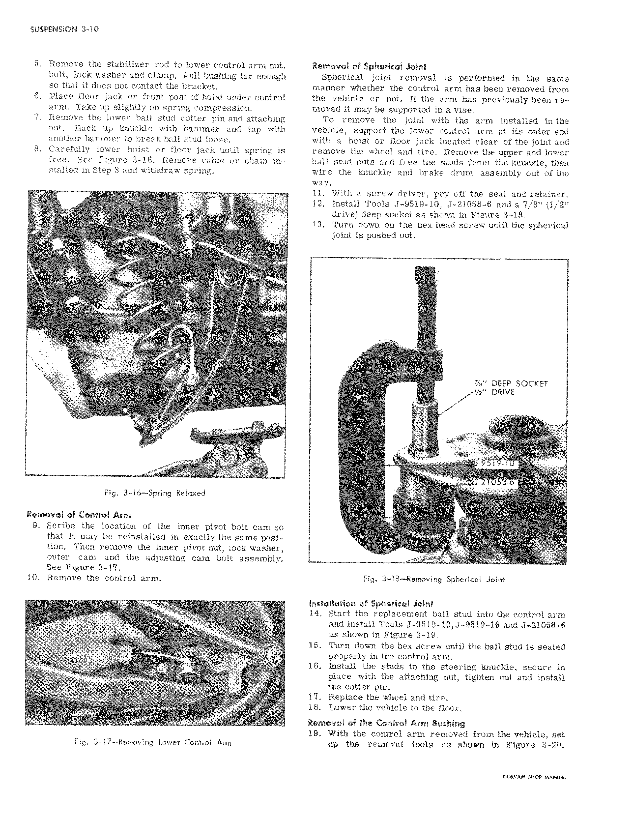
5 Remove the stabilizer rod to lower control arm nut bolt lock washer and clamp Pull bushing far enoug so that it does not contact the bracket 6 Place floor jack or front post of hoist under control arm Take up slightly on spring compression I 7 Remove the lower ball stud cotter pin and attachi nut Back up knuckle with hammer and tap wit another hammer to break ball stud loose 8 Carefully lower hoist or floor jack until spring is free See Figure 3 16 Remove cable or chain installed in Step 3 and withdraw spring I I al Fig 3 16 Spring Relaxed Removal of Control Arm 9 Scribe the location of the inner pivot bolt cam lo that it may be reinstalled in exactly the same position Then remove the inner pivot nut lock washer outer cam and the adjusting cam bolt assembly See Figure 3 17 10 Remove the control arm x s M Fig 3 17 Removing Lower Control Arm I I Ramovaiof Spherical Joint Sphecal joint removal is performed in the same manner whether the control arm has been removed from the ve cle or not If the arm has previously been removed may be supported in a vise To emove the joint with the arm installed in the vehicle support the lower control arm at its outer end with a I hoist or floor jack located clear of the joint and remove the wheel and tire Remove the upper and lower ball st nuts and free the studs from the knuckle then wire t re knuckle and brake drum assembly out of the way 11 With a screw driver pry off the seal and retainer 12 In all Tools J 9519 10 J 21058 6 and a 7 8 1 2 drive deep socket as shown in Figure 3 18 13 Tutn down on the hex head screw until the spherical joint is pushed out e DEEP SOCKET s DRIVE z Fig 3 18 Removing Spherical Joint Installation of Spherical Joint 14 Start the replacement ball stud into the control arm and install Tools J 9519 10 J 9519 18 and J 21058 6 asashown in Figure 3 19 15 Turn down the hex screw until the bail stud is seated properly in the control arm 16 In tall the studs in the steering knuckle secure in place with the attaching nut tighten nut and install the cotter pin 17 R lace the wheel and tire 18 Lower the vehicle to the floor Removdil of the Control Arm Bushing 19 W3th the control arm removed from the vehicle set up the removal tools as shown in Figure 3 20