Jeep Parts Wiki | Ford Parts Wiki
Home | Search | Browse
|
Corvair Chassis Shop Manual December 1964 |
|
Prev

 Next
Next
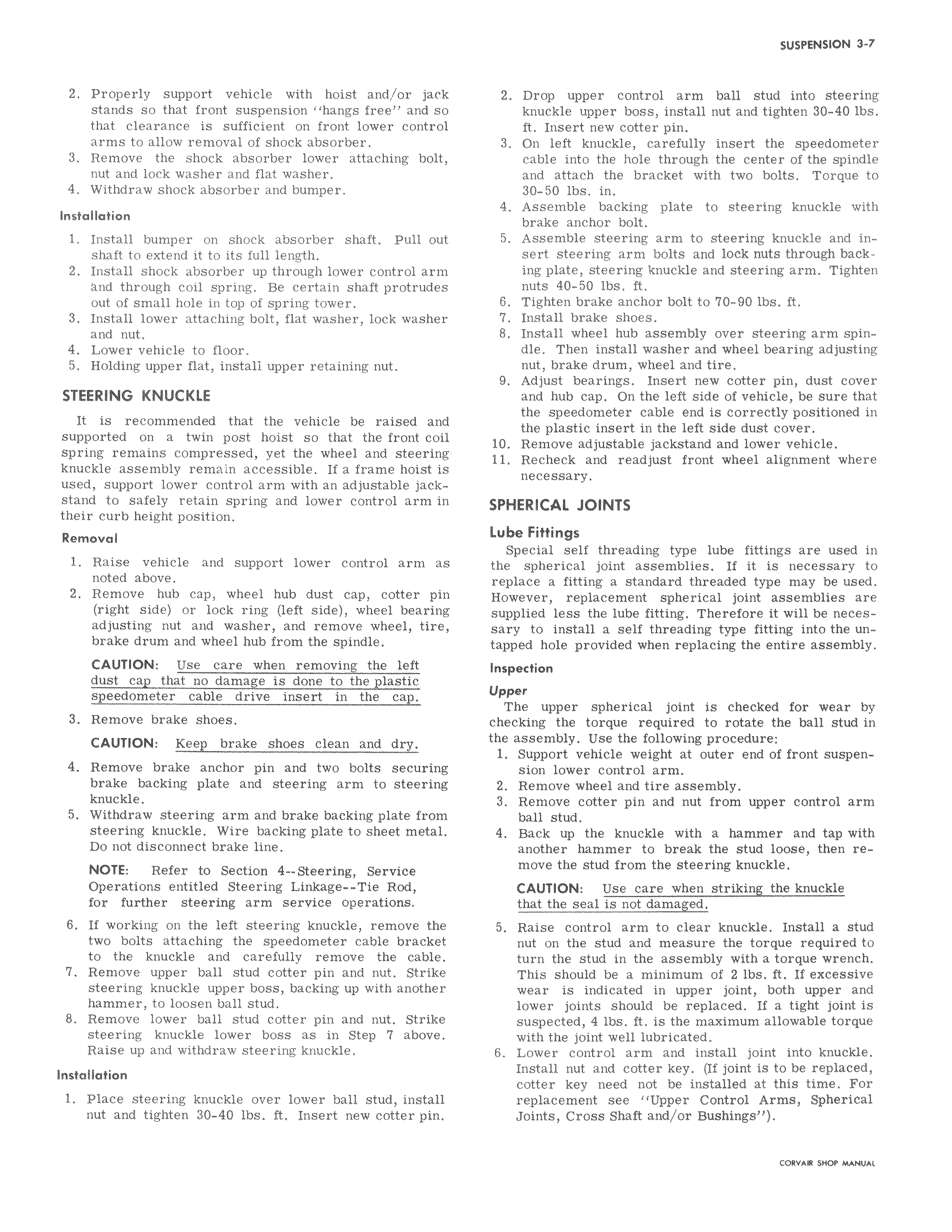
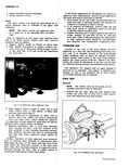
2 Properly support vehicle with hoist and or jack stands so that front suspension hangs free and so that clearance is sufficient on front lower control arms to allow removal of shock absorber 3 Remove the shock absorber lower attaching bolt nut and lock washer and flat washer 4 Withdraw shock absorber and bumper Installation 1 Install bumper on shock absorber shaft Pull out shaft to extend it to its full length 2 Install shock absorber up through lower control arm And through coil spring Be certain shaft protrudes out of small hole in top of spring tower 3 Install lower attaching bolt flat washer lock washer and nut 4 Lower vehicle to floor 5 Holding upper flat install upper retaining nut STEERING KNUCKLE It is recommended that the vehicle be raised and supported on a twin post hoist so that the front coil spring remains compressed yet the wheel and steering knuckle assembly remain accessible If a frame hoist is used support lower control arm with an adjustable jackstand to safely retain spring and lower control arm in their curb height position Removal 1 Raise vehicle and support lower control arm as noted above 2 Remove hub cap wheel hub dust cap cotter pin right side or lock ring left side wheel bearing adjusting nut and washer and remove wheel tire brake drum and wheel hub from the spindle CAUTION Use care when removing the left dust cap that no damage is done to the plastic speedometer cable drive insert in the cap 3 Remove brake shoes CAUTION Keep brake shoes clean and dry 4 Remove brake anchor pin and two bolts securing brake backing plate and steering arm to steering knuckle 5 Withdraw steering arm and brake backing plate from steering knuckle Wire backing plate to sheet metal Do not disconnect brake line NOTE Refer to Section 4 Steering Service Operations entitled Steering Linkage Tie Rod for further steering arm service operations 6 If working on the left steering knuckle remove the two bolts attaching the speedometer cable bracket to the knuckle and carefully remove the cable 7 Remove upper ball stud cotter pin and nut Strike steering knuckle upper boss backing up with another hammer to loosen ball stud 8 Remove lower ball stud cotter pin and nut Strike steering knuckle lower boss as in Step 7 above Raise up and withdraw steering knuckle Installation 1 Place steering knuckle over lower ball stud install nut and tighten 30 40 lbs ft Insert new cotter pin 2 Drop upper control arm ball stud into steering knuckle upper boss install nut and tighten 30 40 lbs ft Insert new cotter pin 3 On left knuckle carefully insert the speedometer cable into the hole through the center of the spindle and attach the bracket with two bolts Torque to 30 50 lbs in 4 Assemble backing plate to steering knuckle with brake anchor bolt 5 Assemble steering arm to steering knuckle and insert steering arm bolts and lock nuts through backing plate steering knuckle and steering arm Tighten nuts 40 50 lbs ft 6 Tighten brake anchor bolt to 70 90 lbs ft 7 Install brake shoes 8 Install wheel hub assembly over steering arm spindle Then install washer and wheel bearing adjusting nut brake drum wheel and tire 9 Adjust bearings Insert new cotter pin dust cover and hub cap On the left side of vehicle be sure that the speedometer cable end is correctly positioned in the plastic insert in the left side dust cover 10 Remove adjustable jackstand and lower vehicle 11 Recheck and readjust front wheel alignment where necessary SPHERICAL JOINTS Lube Fittings Special self threading type lube fittings are used in the spherical joint assemblies If it is necessary to replace a fitting a standard threaded type may be used However replacement spherical joint assemblies are supplied less the lube fitting Therefore it will be necessary to install a self threading type fitting into the untapped hole provided when replacing the entire assembly Inspection Upper The upper spherical joint is checked for wear by checking the torque required to rotate the ball stud in the assembly Use the following procedure 1 Support vehicle weight at outer end of front suspension lower control arm 2 Remove wheel and tire assembly 3 Remove cotter pin and nut from upper control arm ball stud 4 Back up the knuckle with a hammer and tap with another hammer to break the stud loose then remove the stud from the steering knuckle CAUTION Use care when striking the knuckle that the seal is not damaged 5 Raise control arm to clear knuckle Install a stud nut on the stud and measure the torque required to turn the stud in the assembly with a torque wrench This should be a minimum of 2 lbs ft If excessive wear is indicated in upper joint both upper and lower joints should be replaced If a tight joint is suspected 4 lbs ft is the maximum allowable torque with the joint well lubricated 6 Lower control arm and install joint into knuckle Install nut and cotter key Of joint is to be replaced cotter key need not be installed at this time For replacement see Upper Control Arms Spherical Joints Cross Shaft and or Bushings taevsR SHOP MANUAL

 Next
Next