Jeep Parts Wiki | Ford Parts Wiki
Home | Search | Browse
|
Corvair Chassis Shop Manual December 1964 |
|
Prev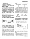
 Next
Next
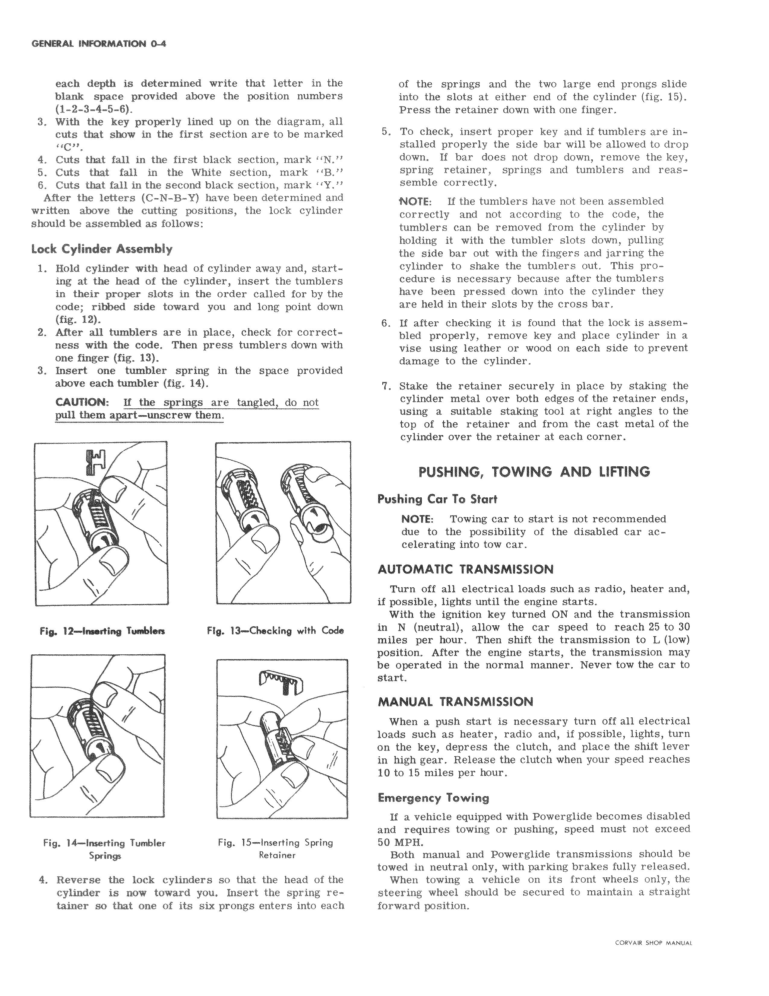
i each depth is determined write that letter in thel blank space provided above the position numbers 1 2 3 4 5 6 3 With the key properly lined up on the diagram alll cuts that show in the first section are to be marked I 4 Cuts that fall in the first black section mark IN 5 Cuts that fall in the White section mark 1B 6 Cuts that fall in the second black section mark I IY After the letters C N B Y have been determined and written above the cutting positions the lock cylinder should be assembled as follows Lock Cylinder Assembly 1 Hold cylinder with head of cylinder away and startl ing at the head of the cylinder insert the tumblers in their proper slots in the order called for by the code ribbed side toward you and long point do7 fig 12 2 After all tumblers are in place check for correct ness with the code Then press tumblers down with one finger fig 13 3 Insert one tumbler spring in the space provide l above each tumbler fig 14 I CAUTION If the springs are tangled do not pull them apart unscrew them 1 1 W Fio 12 Iimtina Tuabhs Fig 13 Checking with Co1 s v i maw Fig 14 Inserting Tumbler Fig 15 Inserting Spring I Springs Retainer 4 Reverse the lock cylinders so that the head of the cylinder is now toward you Insert the spring retainer so that one of its six prongs enters into each of the springs and the two large end prongs slide into the slots at either end of the cylinder fig 15 Press the retainer down with one finger 5 To check insert proper key and if tumblers are instalked properly the side bar will be allowed to drop down If bar does not drop down remove the key spring retainer springs and tumblers and reassemble correctly NOTE If the tumblers have not been assembled corTectly and not according to the code the tumblers can be removed from the cylinder by holding it with the tumbler slots down pulling the side bar out with the fingers and jarring the cyl nder to shake the tumblers out This procedure is necessary because after the tumblers have been pressed down into the cylinder they are held in their slots by the cross bar 6 If after checking it is found that the lock is assembled properly remove key and place cylinder in a vise using leather or wood on each side to prevent damage to the cylinder 7 Stake the retainer securely in place by staking the cylinder metal over both edges of the retainer ends usi ng a suitable staking tool at right angles to the top of the retainer and from the cast metal of the cylinder over the retainer at each corner PUSHINGr TOWING AND LIFTING Pushing Car To Start NOTE Towing car to start is not recommended due to the possibility of the disabled car acceJerating into tow car AUTOMATIC TRANSMISSION Turn off all electrical loads such as radio heater and if possible lights until the engine starts With the ignition key turned ON and the transmission in N neutral allow the car speed to reach 25 to 30 miles per hour Then shift the transmission to L low position After the engine starts the transmission may be opeicated in the normal manner Never tow the car to start t MANUAL TRANSMISSION Wheo a push start is necessary turn off all electrical loads such as heater radio and if possible lights turn on the 1 key depress the clutch and place the shift lever in hig4 gear Release the clutch when your speed reaches 10 to 16 miles per hour Emergency Towing If a vehicle equipped with Powerglide becomes disabled and requires towing or pushing speed must not exceed 50 MPII Bottj manual and Powerglide transmissions should be towed in neutral only with parking brakes fully released Wheh towing a vehicle on its front wheels only the steer wheel should be secured to maintain a straight forwaifd position