Jeep Parts Wiki | Ford Parts Wiki
Home | Search | Browse | Marketplace | Messages | FAQ | Guest
Prev
 Next
Next
3735440
3735440
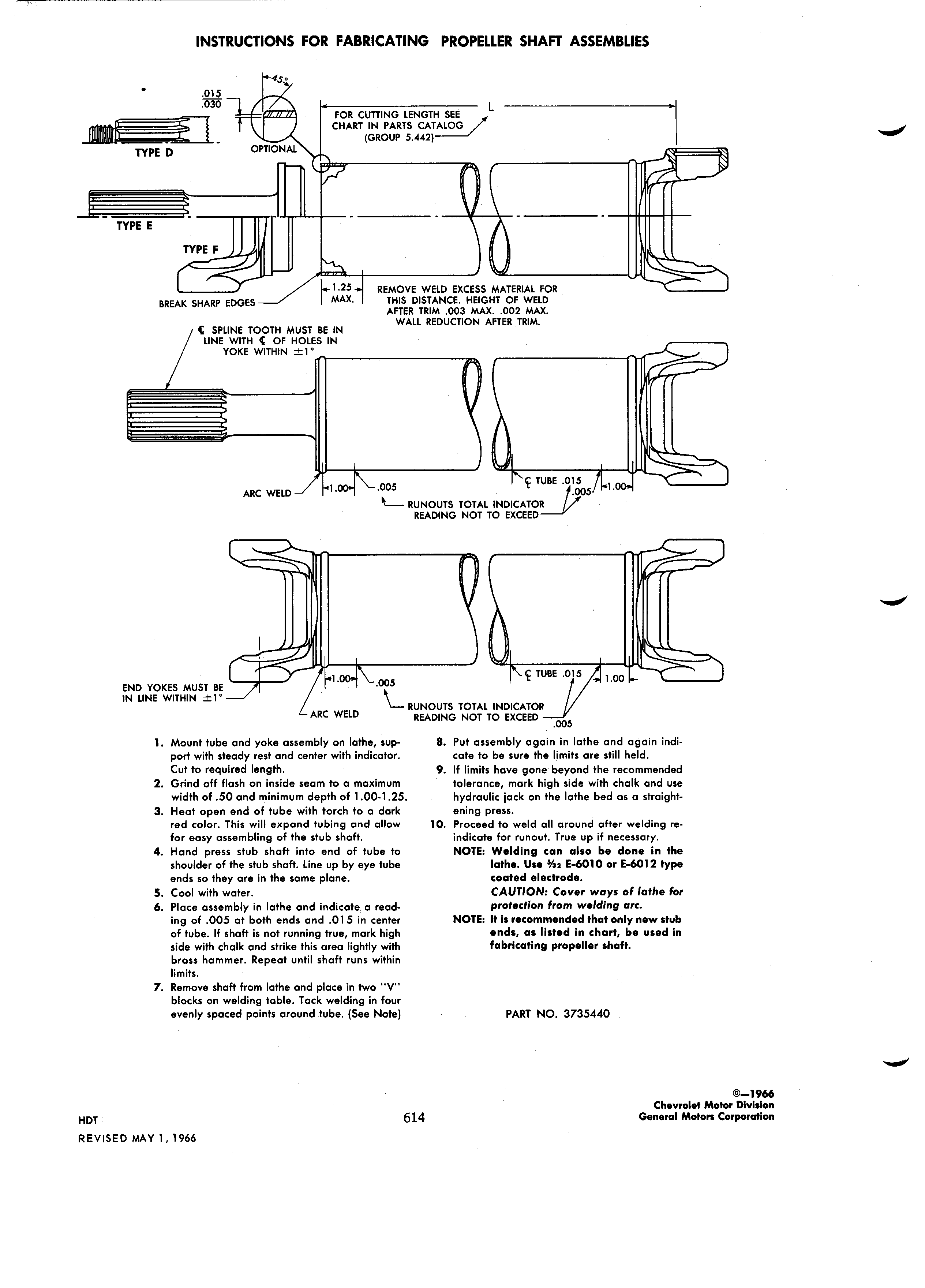
INSTRUCTIONS FOR FABRICATING PROPELLER SHAFT ASSEMBLIES 45 E 030 L wm ron currino LENGTH sez CHART IN PARTS CATALOG GROUP 5 442 OPTIONAL 1 TYPE D 3 I s I l l TYPE E Ir TYPE E ld I 25 REMOVE WELD EXCESS MATERIAL ron A BREAK SHARP E eEs MM mis DISTANCE HEIGHT or wm AFTER TRIM oos MAx ooz MAx WALL REDUCTION AFTER TRIM I SPLINE room Must BE IN une wm I I or mores IN vc I E WITHIN I g runs 015 ARC WELD 1 005 005 l M RUNOUTS rom INDICATOR READING Nor TO EXCEED I I I lll ll I 0 5 2 TUBE 5 0 END vo Es Must as IN LINE wimm tv RUNOUTS rom INDICATOR ARC WELD READING Nor ro EXCEED oo5 I Mount tube and yoke assembly on lathe sup 8 Put assembly again in lathe and again indi port with steady rest and center with indicator cate to be sure the limits are still held Cut to required length 9 lf limits have gone beyond the recommended 2 Grind off flash on inside seam to a maximum tolerance mark high side with chalk and use width of 50 and minimum depth of l OO l 25 hydraulic iack on the lathe bed as a straight 3 Heat open end of tube with torch to a dark ening press red color This will expand tubing and allow I0 Proceed to weld all around after welding re far easy assembling of the stub shaft indicate for runout True up if necessary 4 Hand press stub shaft into end of tube to NOTE Welding can also be done in the shoulder ofthe stub shaft Line up by eye tube lathe Use VI E 60 l0 or E 60 2 type ends so they are in the same plane coated electrode 5 Cool with water CAUTION Cover ways of lathe for 6 Place assembly in lathe and indicate a read P ll fI m W ldl 9 WF ing of 005 at both ends and 0l 5 in center NOTE It is recommended that only new stub of tube lf shaft is not running true mark high ends as listed in chart be used in side with chalk and strike this area lightly with f brl tll 9 propeller shaft brass hammer Repeat until shaft runs within limits 7 Remove shaft from lathe and place in two V blocks on welding table Tack welding in four evenly spaced points around tube See Note PART NO 3735440 3 was Chevrolet Motor Division HD 614 General Motors Corporation REvIsE MAY 1 1966