Jeep Parts Wiki | Ford Parts Wiki
Home | Search | Browse
|
Corvair Chassis Shop Manual Supplement December 1967 |
|
Prev
 Next
Next
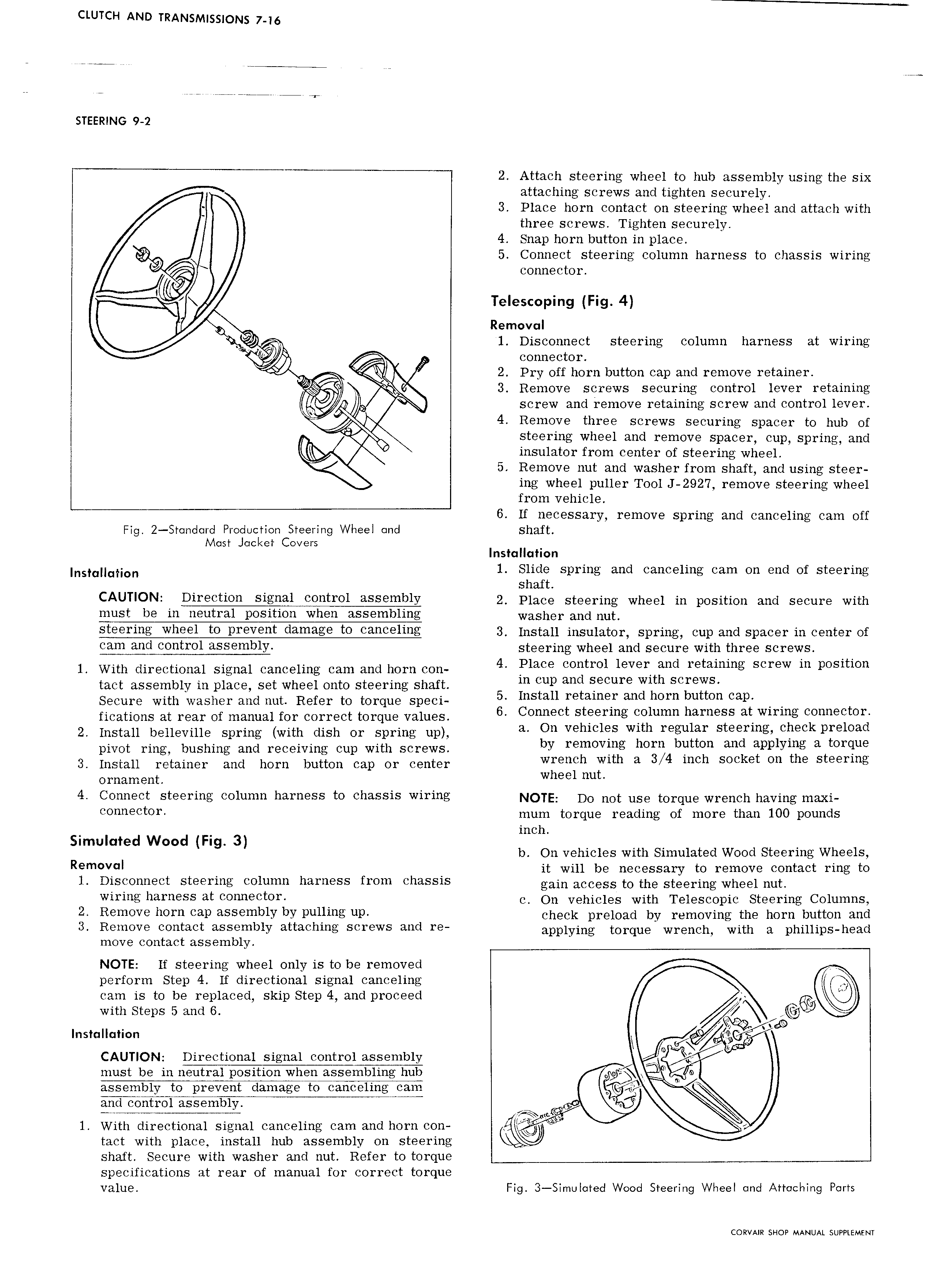
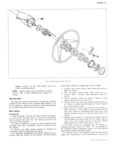
CLUTCH AND TRANSMISSIONS 7 16 STEERLNG 9 2 2 Attach steering wheel to hub assembly using the six attaching screws and tighten securely I 3 Place horn contact on steering wheel and attach with three screws Tighten securely 4 Snap horn button in place K 5 Connect steering column harness to chassis wiring connector i Telescoping Fig 4 Removal O i 6 1 Disconnect steering column harness at wiring connector 2 Pry off horn button cap and remove retainer 3 Remove screws securing control lever retaining I Q screw and remove retaining screw and control lever 4 Remove three screws securing spacer to hub of i steering wheel and remove spacer cup spring and insulator from center of steering wheel 5 Remove nut and washer from shaft and using steer ing wheel puller Tool J 2927 remove steering wheel from vehicle 6 If necessary remove spring and canceling cam off Fig 2 t nclard Production Steering Wheel and shaft Mast l cl et Covers I t H F ns a a ion installation 1 Slide spring and canceling cam on end of steering shaft CAUTl0N DUQCUOU Signal eentrel 9 S mb1Y 2 Place steering wheel in position and secure with must be in neutral position when assembling Waghgy and out Steering wheel te prevent dame ee te eeneeline 3 meten insulator spring eup and spacer in center er cam and control assembly steering wheel and secure with three screws 1 With directional signal canceling cam and horn con 4 Place Control lever and retemme Screw m FOSIUOH tact assembly in place set wheel onto steering shaft m wp and Secure wth SCr WS Secure with washer and nut Refer to torque speci 5 Install I tam r and hem buttee Cap fieations at rear of manual for correct torque v 1u S 6 C0 t Steeflllg 01umn harness at wiring connector 2 Install belleville spring with dish or spring up a On vehieiee Wlth regular St rmg Cheek pmmad pivot ring bushing and receiving cup with screws by rgmovtng here btltton and applymg 3 tereue 3 Install retainer and horn button cap or center W e eh yuh 3 3 4 meh Seeket ee the Steermg ornament W B6 mh 4 Connect steering column harness to chassis wiring NOTE Do not use torque Wrench having maxi connector mum torque reading of more than 100 pounds inch Simulated Wood Fi 3 g b On vehicles with Simulated Wood Steering Wheels Removal it will be necessary to remove contact ring to 1 Disconnect steering column harness from chassis goin uooess to the steering Wh G1nut wlrmg harness et CO m CtOY c On vehicles with Telescopic Steering Columns 2 Relneve hOm Cap 3 SS mb1Y by Pulling uP check preload by removing the horn button and 3 Remove contact assembly attaching screws and re eppiyirig torque Wreueiu with e piiiiiipsmead move contact assembly NOTE lf steering wheel only is to be removed perform Step 4 If directional signal canceling cam is to be replaced skip Step 4 and proceed with Steps 5 and 6 gw Installation CAUTION Directional signal congol assemw Q V must be in neutral position whgiissembling hub U W e assembly to prevent damage to canceling cam rE 6HEFiE mb1y 4 W 1 With directional signal canceling cam and horn con 1 tact with place install hub assembly on steering shaft Secure with washer and nut Refer to torque specifications at rear of manual for correct torque value Fig 3 Simuloted Wood Steering Wheel and Attaching Ports CORVAIR SHOP MANUAL SUPPLEMENT