Jeep Parts Wiki | Ford Parts Wiki
Home | Search | Browse
|
Corvair Chassis Shop Manual Supplement December 1967 |
|
Prev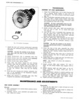
 Next
Next
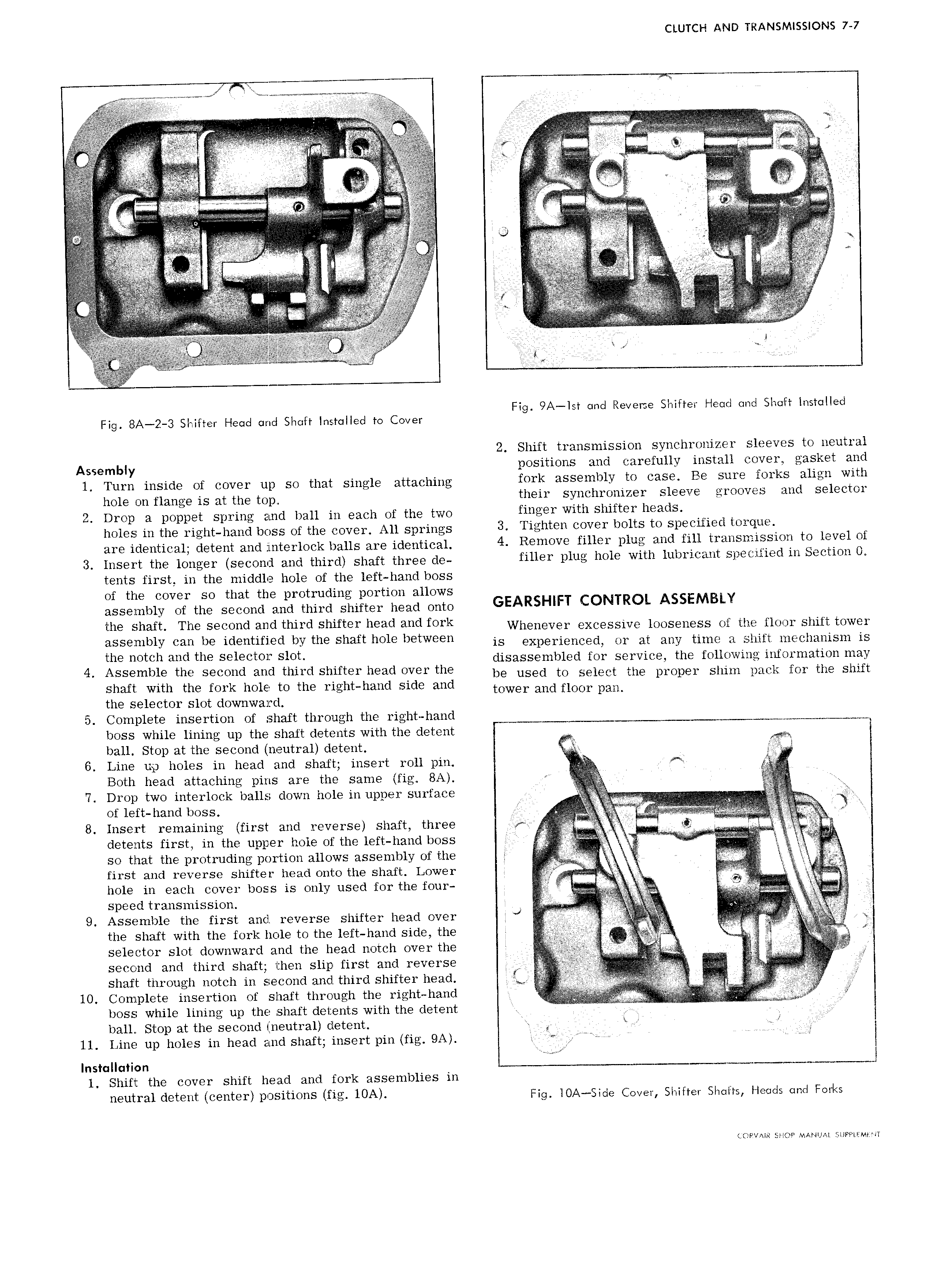
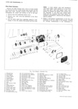
CLUTCH AND TRANSMISSIONS 7 7 w W W C CCC C C Caf i Ca a a C la iCt aCarsCa aC aCC W 1 C S CC C C A C C C i to V i if e A CCCC S C L C t C Cg C C C C M C T CC CCCCC CCCC CC hi C C C C C C C C C CCCCC L C C C C C 4 CC 1 i C CV C t A C CClC C C C CCCCC J C CCC S C i C iC L Ti tilcf C CCCC CCCC C C CC CC C Cr C N i L A V W C ir C CCC C V C if e Fig 9 ist and Reverse Shifter Head and Shaft installed Fig 8A 2 3 Shifter Head and Shaft Installed to Cover 2 Shift transmission synchronizer sleeves to neutral Asggmmy positions and carefully install cover gasket and l Turn inside of cover up so that single attaching f0l k 21SS lllb1Y tc C3S Be S ll OILS align with hola gn flange is at the wp their synchronizer sleeve grooves and selector 2 Drop a poppet spring and ball in each of the two flll l with Shifter h tdS holes in the right hand boss of the cover All springs 3 Tighten ccver lcclte te Specified terque ara identical datant and inCtar1dak balls are identical 4 Renncvc filler plus and fill treneneleeten te level Ol 3 Insert the longer second and third shaft three da filler plus ncle with lulnecelnt S1 ecifle lln Sectlee 0 tents first in the middle hole of the left hand boss of the cover so that the protruding portion allows assembly of the second and third shifter head onto GEARSHIFT CONTROL ASSEMBLY the Shaft The Seeend ehd third Shifter heed and ferk Whenever excessive looseness of the floor shift tower assembly hah be ldehtlhed by the Shaft hele between is experienced or at any time a shift mechanisin is the hetch and the Selector Sleh disassembled for service the following information may 4 Assembie the Secehd and thlrd Shifter heed ever the be used to select the proper shim pack for the shift shaft with the fork hole to the r 1ght hand side and towel and HOO PML the selector slot downward 5 Complete insertion of shaft through the right hand w boss while lining up the shaft detents with the detent miM M ball Stop at the second neutral detent 6 Line up holes in head and shaft insert roll pin Both head attaching pins are the same fig 8A r L 7 Drop two interlock balls down hole in upper surface V V of left hand boss s CC 8 Insert remaining first and reverse shaft three xt detents first in the upper hole of the left hand boss J Q so that the protruding portion allows assembly of the 1 i 2 first and reverse shifter head onto the shaft Lower C CCC R C 1 hole in each cover boss is only used for the four L i i Speed trensnueslcn C CC C i C 9 Assemble the first and reverse shifter head over J E the shaft with the fork hole to the left hand side the 1 ZC M a selector slot downward and the head notch over the k p j C second and third shaft then slip first and reverse W i ii i i ini C Qi shaft through notch in second and third shifter head 5 l ii 10 Complete insertion of shaft thI O Llgh ih I l ht h9 lid niii boss while lining up the shaft detents with the detent C Ci ei L ball Stop at the second neutral detent C CCCr at L 11 Line up holes in head and shaft insert pin fig 9A et Q Cl i Installation i 1 Shift the cover shift head and fork assemblies in neutral detent center pcsiticns fla l0A rag 10A sada cava shirtat share naads and Forks L F V l SHOP MAMUA UPPiEMr iT