Jeep Parts Wiki | Ford Parts Wiki
Home | Search | Browse
|
Corvair Chassis Shop Manual Supplement December 1967 |
|
Prev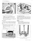
 Next
Next
11111111
11111111
111111
111111
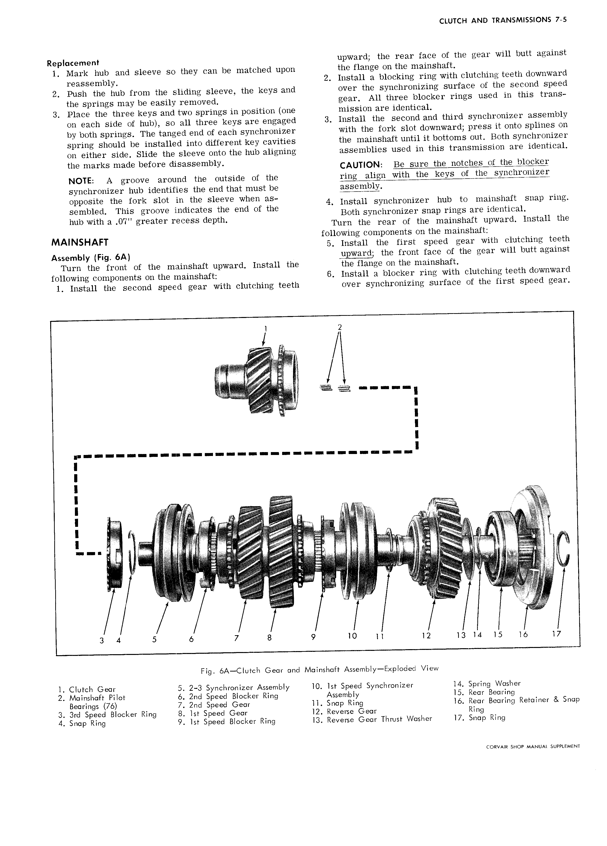
CLUTCH AND TRANSMISSIONS 7 5 Replacement upward the rear face of the gear will butt against 1 Mark hub and sleeve so they can be matched upon the flange on the mainshaft reassembly 2 Install a blocking ring with clutching teeth downward 2 Push the hub from the sliding sleeve the keys and over the synchronizing surface of the second speed the springs may be easily removed gear All three blocker rings used in this trans 3 Place the three keys and two springs in position one mission are identical on each side of hub so all three keys are engaged 3 Install the second and third synchronizer assembly by both springs The tanged end of each synchronizer with the fork slot downward press it onto splines on spring should be installed into different key cavities the mainshaft until it bottoms out Both synchronizer on either side Slide the sleeve onto the hub aligning assemblies used in this transmission are identical the marks made before disassembly CAUTION BG Sure the notches Of Edmgkg NOTE groove around the outside of the ring align with the keys of tl L B l I QI I synchronizer hub identifies the end that must be E Oplwslte the fork Slot m th Sleeve when gsi 4 Install synchronizer hub to mainshaft snap ring sembled This groove indicates the end of the I hub with 3 0 greater mpess depth Both syncnronizer snap rings are identica Turn the rear of the mainshaft upward Install the M A following components on the mainshaft l NSHAFT 5 Install the first speed gear with clutching teeth Assembly Fig 6A upward the front face of the gear will butt against Turn the front of the mainshaft upward Install the the flange on the niainshaft following components on the mainshaft 6 Install a blocker ring with clutching teeth downward 1 Install the second speed gear with clutching teeth over synchronizing surface of the first speed gear j 2 I I I I IIKIKKXZZK 11111111111111 XYKYXZJ I I I A i i I I V Q i Q I H il I T I litt ii t r l rlli l l jr ltr Fg i l k if t i zz i t 5 t E Sw S I l i N 1 A V 3 4 5 6 7 8 9 10 ii l2 13 ld 15 16 l7 l Fig 6A Clutch Gear and Mainshatt Assemloly E ploded View l Clutch Gear 5 2 3 Synchronizer Assembl lO lst S eed S nchronizer l4 S rin Washer Y P Y P Q 2 Mainshaft Pilot 6 2nd Speed Blocker Ring Assembly l5 Rear Bearing Bearings 76 7 2nd Speed Gear ll Snap Ring l6 Rear Bearing Retainer Snap 3 3rd Speed Blocker Ring 8 lst Speed Gear l2 Reverse Gear Ring 4 Snap Ring 9 lst Speed Blocker Ring I3 Reverse Gear Thrust Washer l7 Snap Ring CORVAKR SHOP MANUAI SUPPLEMENT