Jeep Parts Wiki | Ford Parts Wiki
Home | Search | Browse
|
Corvair Chassis Shop Manual Supplement December 1967 |
|
Prev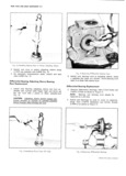
 Next
Next
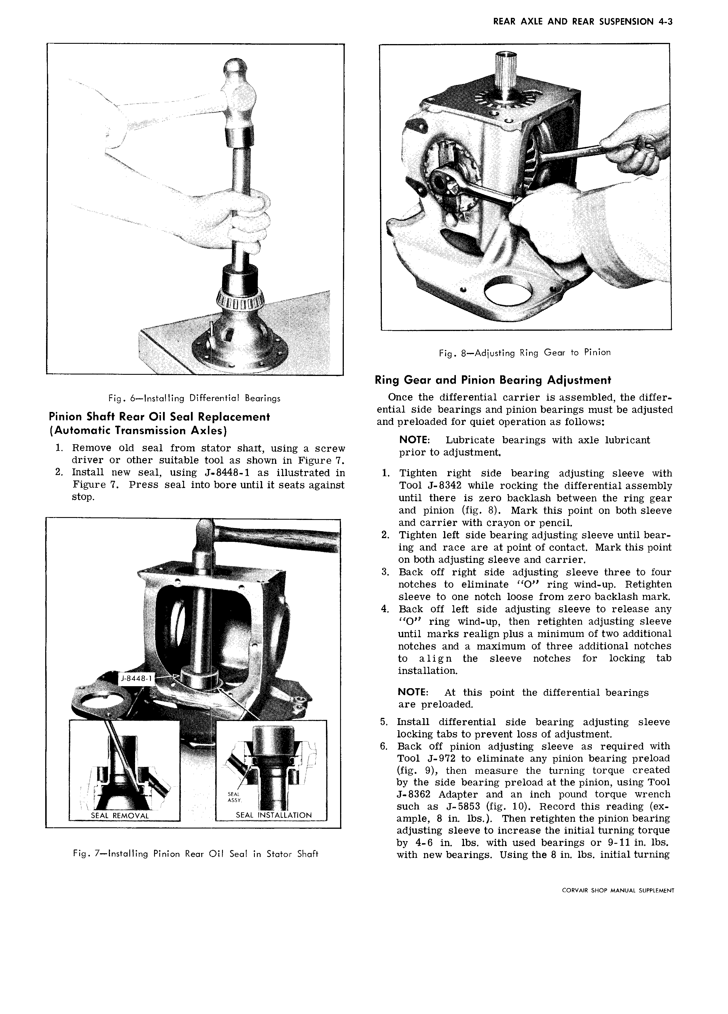
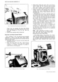
REAR AXLE AND REAR SUSPENSION 4 3 1A jj 9 SSR V V g A xg MA W I g rr krkkrrr ii gk i In M q R A RR S R il l M R RSS A RS R c A S A A l R as is AS A E AAA L R S S ESSS i at E RS RSSRR L L v 2i Ri 7ur wGM N n p ew r A M JR A A A L R S S S S S S ERESA SS RRSA ES A L I AA 4 E RSRS R S SSRR iRLr i VyS v LZAA Fig 8 Aoliusting Ring Gear to Pinion Ring Gear and Pinion Bearing Adjustment Fig 6 lnsr Iling Differential Bearings Once the differential carrier is assembled the differ ential side bearings and pinion bearings must be adjusted PLm Shen Rec Q l R P m l and preloaded for quiet operation as follows Automatic Transmission Axles NOTE Lubricate bearings with axle lubricant 1 Remove old seal from stator shart using a screw prim to adjustment driver or other suitable tool as shown in Figure 7 2 Install new seal using J 8448 1 as illustrated in 1 Tighten right side bearing adjusting sleeve with Figure 7 Press seal into bore until it seats against Tool J 8342 while rocking the differential assembly stop until there is zero backlash between the ring gear and pinion fig 8 Mark this point on both sleeve and carrier with crayon or pencil j 2 F 2 Tighten left side bearing adjusting sleeve until bear H ing and race are at point of contact Mark this point i on both adjusting sleeve and carrier i R lj jp y A L rr 3 Back off right side adjusting sleeve three to four ii i notches to eliminate O ring wind up Retighten ig sleeve to one notch loose from zero backlash mark 4 Back off left side adjusting sleeve to release any O ring wind up then retighten adjusting sleeve Vi until marks realign plus a minimum of two additional l A ZA notches and a maximum of three additional notches Q Ql to align the sleeve notches for locking tab L8448 I A installation R at TL NOTE At this point the differential bearings rr are i r 1 d d A ii V v H 5 Install differential side bearing adjusting sleeve Z Q R locking tabs to prevent loss of adjustment j fj 2 ig 6 Back off pinion adjusting sleeve as required with 1 A A w i 4 A il Tool J 972 to eliminate any pinion bearing preload Q fig 9 then measure the turning torque created Y Q B i by the side bearing preload at the pinion using Tool j 2 j 6 J 8362 Adapter and an inch pound torque wrench 7 1 l such as J 5853 fig 10 Record this reading ex SEAL REMOVAL SEAL LNSTALLATLON ample 8 in lbs Then retighten the pinion bearing adjusting sleeve to increase the initial turning torque by 4 6 in lbs with used bearings or 9 11 in lbs Fig 7 Installing Pinion Rear Oil Seal in Stator Shaft with new bearings Using the 8 in lbs initial turning CORVAIR SHOP MANUAL SUPPLEMENT