Jeep Parts Wiki | Ford Parts Wiki
Home | Search | Browse | Marketplace | Messages | FAQ | Guest
|
Corvair Chassis Shop Manual Supplement December 1966 |
|
Prev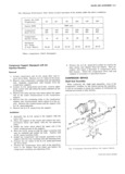
 Next
Next
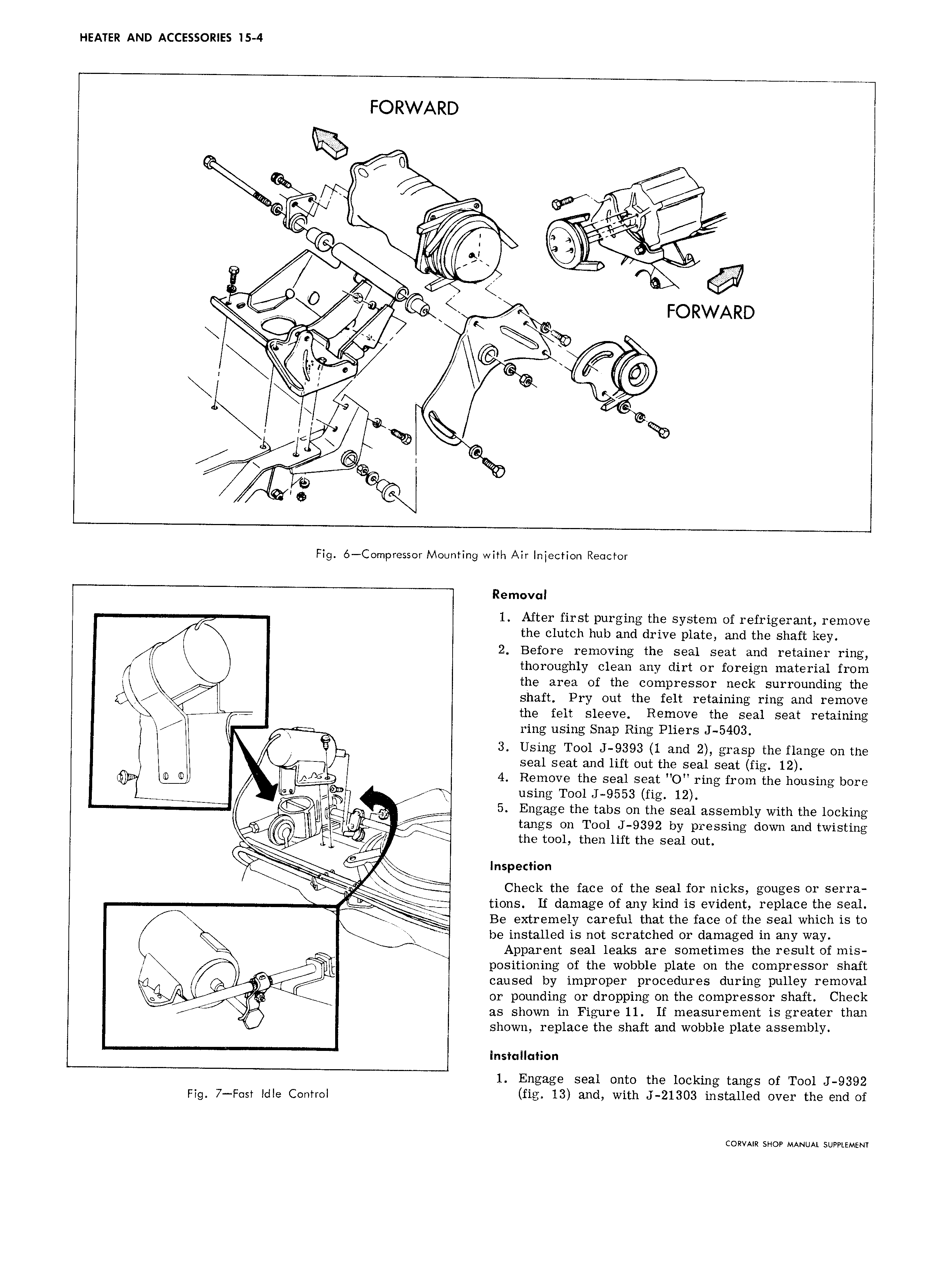
HEATER AND ACCESSORIES is 4 FORWARD I lh wmnrv I k r Z E E NI l 4 I i I P it A w L ev K FORWARD l T x J I I Y K r Q 1 l I 9 G Fig 6 Compressor Mounting with Air Injection Reactor Removal f 1 After first purging the system of refrigerant remove the clutch hub and drive plate and the shaft key 2 Before removing the seal seat and retainer ring thoroughly clean any dirt or foreign material from the area of the compressor neck surrounding the I shaft Pry out the felt retaining ring and remove the felt sleeve Remove the seal seat retaining ring using Snap Ring Pliers J 5403 3 Using Tool J 9393 1 and 2 grasp the flange on the V seal seat and lift out the seal seat fig 12 o gg 4 Remove the seal seat O ring from the housing bore I using Tool J 9553 fig 12 ri I I 5 Engage the tabs on the seal assembly with the locking M N tangs on Tool 9392 by pressing down and twisting I 4 the tool then lift the seal out R ci 1 Inspection J5 Im Check the face of the seal for nicks gouges or serra L tions If damage of any kind is evident replace the seal t Be extremely careful that the face of the seal which is to be installed is not scratched or damaged in any way X Apparent seal leaks are sometimes the result of mis I 1 positioning of the wobble plate on the compressor shaft l caused by improper procedures during pulley removal ig 6 or pounding or dropping on the compressor shaft Check as shown in Figure 11 If measurement is greater than shown replace the shaft and wobble plate assembly installation 1 Engage seal onto the locking fangs of Tool J 9392 p g 7 g Sy idle Control fig 13 and with J 21303 installed over the end of CORVAIR SHOP MANUAL SUPPLEMENT