Jeep Parts Wiki | Ford Parts Wiki
Home | Search | Browse | Marketplace | Messages | FAQ | Guest
|
Corvair Chassis Shop Manual Supplement December 1966 |
|
Prev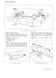
 Next
Next
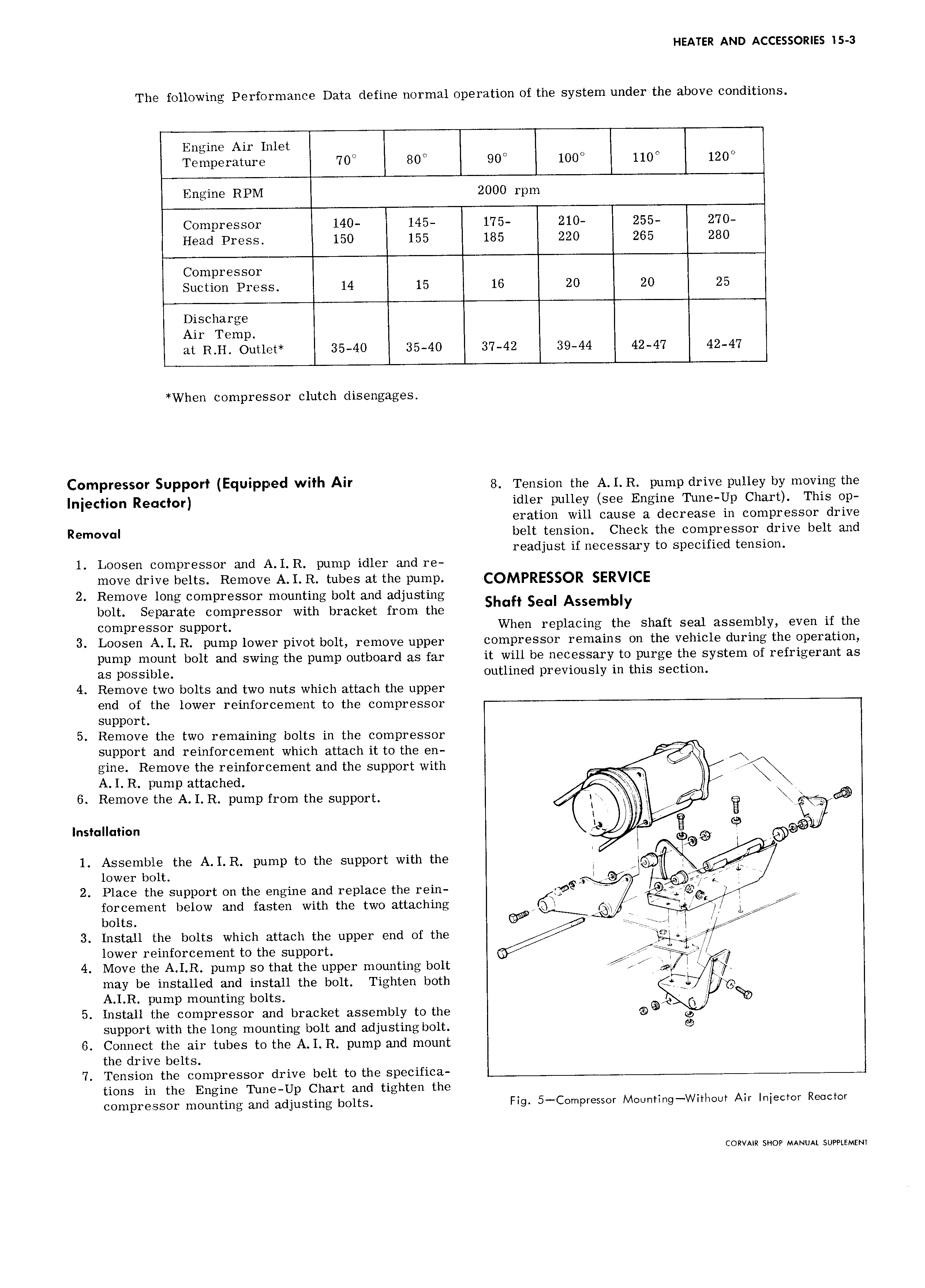
HEATER AND ACCESSORIES 15 3 The following Performance Data define normal operation of the system under the above conditions Engine Air Inlet Temperature 70 80 l00 110 1200 Engine RPM 2000 rpm Compressor 140 145 175 210 255 270 Head Press 150 155 185 220 265 280 Compressor Suction Press 14 15 16 20 20 25 Discharge Air Temp at R H Outlet 35 40 35 40 37 42 39 44 42 47 42 47 When compressor clutch disengages C mP e SUPP I IE IUIPF d with Air 8 Tension the A I R pump drive pulley by moving the Infection Reactor idler pulley see Engine Tune Up Chart This op eration will cause a decrease in compressor drive Removal belt tension Check the compressor drive belt and readjust if necessary to specified tension 1 Loosen compressor and A I R pump idler and re move drive belts Remove A I R tubes at the pump COMPRESSOR SERVICE 2 Remove long compressor mounting bolt and adjusting bolt Separate compressor with bracket from the Shah seul Assembly compressor support When replacing the shaft seal assembly even if the 3 Loosen A I R pump lower pivot bolt remove upper compressor remains on the vehicle during the operation pump mount bolt and swing the pump outboard 35 far it will be necessary to purge the system of refrigerant as as possible outlined previously in this section 4 Remove two bolts and two nuts which attach the upper end of the lower reinforcement to the compressor support 5 Remove the two remaining bolts in the compressor support and reinforcement which attach it to the en J gine Remove the reinforcement and the support with A I R pump attached l x 6 Remove the A I R pump from the support nixk Ia E lnsf II 1i0n 9 I E Q p 1 Assemble the A I R pump to the support with the 3 lower bolt I 5 l 2 Place the support on the engine and replace the rein S 2 e gq I K k forcement below and fasten with the two attaching mfr V 7 X bolts WW V I I 1 I 7 3 Install the bolts which attach the upper end of the I lower reinforcement to the support if 4 Move the A I R pump so that the upper mounting bolt may be installed and install the bolt Tighten both I JH 5 A I R pump mounting bolts r Rap 5 Install the compressor and bracket assembly to the Q support with the long mounting bolt and adjusting bolt 9 6 Connect the air tubes to the A I R pump and mount the drive belts 7 Tension the compressor drive belt to the specifica tions in the Engine Tune Up Chart and tighten the COIHpI SSOI mounting QLIICI adjusting bolts Fig 5 C0mpressor Mounting WitIaout Air Injector Reactor CORVAIR SHOP MANUAL SUPPLEMENT