Jeep Parts Wiki | Ford Parts Wiki
Home | Search | Browse
|
Corvair Chassis Shop Manual Supplement December 1966 |
|
Prev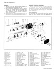
 Next
Next
3869499
3869499
8877877
8877877
3872878
3872878
3872879
3872879
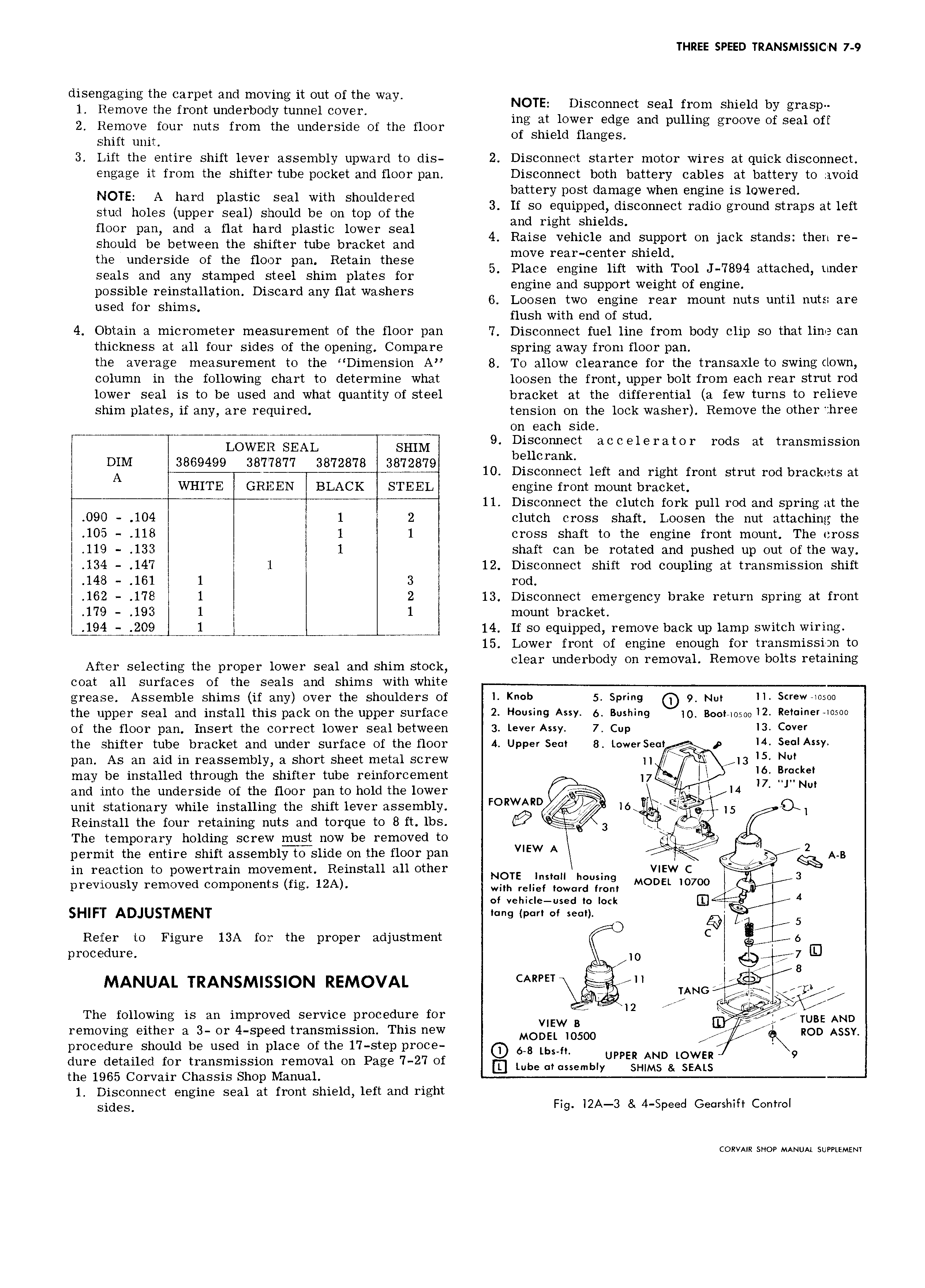
THREE SPEED TRANSMISSION 7 9 disengaging the carpet and moving it out of the wa 1 Remove the front underbody tunnel cover Y NOTE Dlscomwct Seal fllom Shleld by grasp 2 Remove four nuts from the underside of the floor mg at www edge and puumg groove Of Seal Off Shift mm of shield flanges 3 Lift the entire shift lever assembly upward to dis 2 Disconnect starter motor wires at quick disconnect engage it from the shifter tube pocket and floor pan Disconnect both battery cables at battery to avoid NOTE A hard plastic seal with shouldered 3 Eattery pgst damfge when englpe IS lowered Stud holes upper Seal should be On mp Of the so equipped disconnect radio ground straps at left floor pan and a flat hard plastic lower seal 4 gm mghth laleldszj should be between the shifter tube bracket and mif rgirligntiz Siglglziort On Jack stands then m gzilsunssgsgig 3 11 951 O 1 gmghmlfifxx ghigi 5 Place engine lift with Tool J 7894 attached under possible reinstallation Discard any flat washers 6 i1 naIE vSuppQ t Welght O lgngimth t tl ut 6 use for shims Hush With i 1 i f S 4 Obtain a micrometer measurement of the floor pan 7 Disconnect fuel line from body clip so that line can thickness at all four sides of the opening Compare spring away from floor pan the average measurement to the Dimension A 8 To allow clearance for the transaxle to swing clown column in the following chart to determine what loosen the front upper bolt from each rear strut rod lower seal is to be used and what quantity of steel bracket at the differential a few turns to relieve shim plates if any are required tension on the lock washer Remove the other three on each side nu C LOWER SEAL EHIM 9 Disconnect accelerator rods at transmission DIM 3869499 8877877 3872878 3872879 b u m k A 10 Disconnect left and right front strut rod brackets at l WHITE GREEN BLACK S I EEL engine front mount bracket J 11 Disconnect the clutch fork pull rod and spring at the O9 D 104 z 1 2 clutch cross shaft Loosen the nut attaching the 105 118 1 1 cross shaft to the engine front mount The cross l 119 133 1 shaft can be rotated and pushed up out of the way 134 147 1 12 Disconnect shift rod coupling at transmission shift 1413 161 1 3 rod I 1612 178 1 I 2 13 Disconnect emergency brake return spring at front 179 193 1 1 mount bracket ji 209 L l 14 If so equipped remove back up lamp switch wiring 15 Lower front of engine enough for transmission to After selecting the proper lower seal and shim stock Clear Lmderbody On removal Remove bolts retammg coat all surfaces of the seals and shims with white grease Assemble shims if any over the shoulders of 1 Knob 5 Spring 9 Nut I1 Screwaosoo the upper seal and install this pack on the upper surface 2 Housing Assy 0 Bushing O 300 0500 12 Retainer 10500 of the floor pan Insert the correct lower seal between 3 Lever Assy 7 Cup I3 Cover the shifter tube bracket and under surface of the floor 4 Upper Sec 8 L0werSe l I4 Se Assy pan As an aid in reassembly a short sheet metal screw H 3 5 NW may be installed through the shifter tube reinforcement 17 f k and into the underside of the floor pan to hold the lower g I4 J N unit stationary while installing the shift lever assembly FORWARD 16 L 7S Q I5 L Reinstall the four retaining nuts and torque to 8 ft lbs 3 l The temporary holding screw must now be removed to permit the entire shift assemblwslide on the floor pan WEW A Eg 2 A in reaction to powertrain movement Reinstall all other NO view C W TE Inslcnll housing 3 previously removed components fig 12A wm relief mwcrd from MODEL l0700 4 4 of vehicle used to lock SHIFT ADJUSTMENT e r r f sw mgg 5 Refer to Figure 13A for the proper adjustment D C 0 procedure 10 7 D 8 l CARPET 7 MANUAL TRANSM SlON REMOVAL lANGi g The following is an improved service procedure for 12 CC i TLLE AND removing either a 3 or 4 speed transmission This new MO v 2O O0 ROD AS y procedure should be used in place of the 1 7 step proce QD 6 8 lbs f dure detailed for transmission removal on Page 7 27 of L L b UPPER AND LOWER 9 u e of cssembly M5 3 EA the 1965 Corvair Chassis Shop Manual 1 Disconnect engine seal at front shield left and right Sjd S Fig l2A 3 8 4 Speed Georshift Control CORVAIR SHOP MANUAL SUPPLEMENT