Jeep Parts Wiki | Ford Parts Wiki
Home | Search | Browse | Marketplace | Messages | FAQ | Guest
|
Corvair Chassis Shop Manual Supplement December 1966 |
|
Prev

 Next
Next
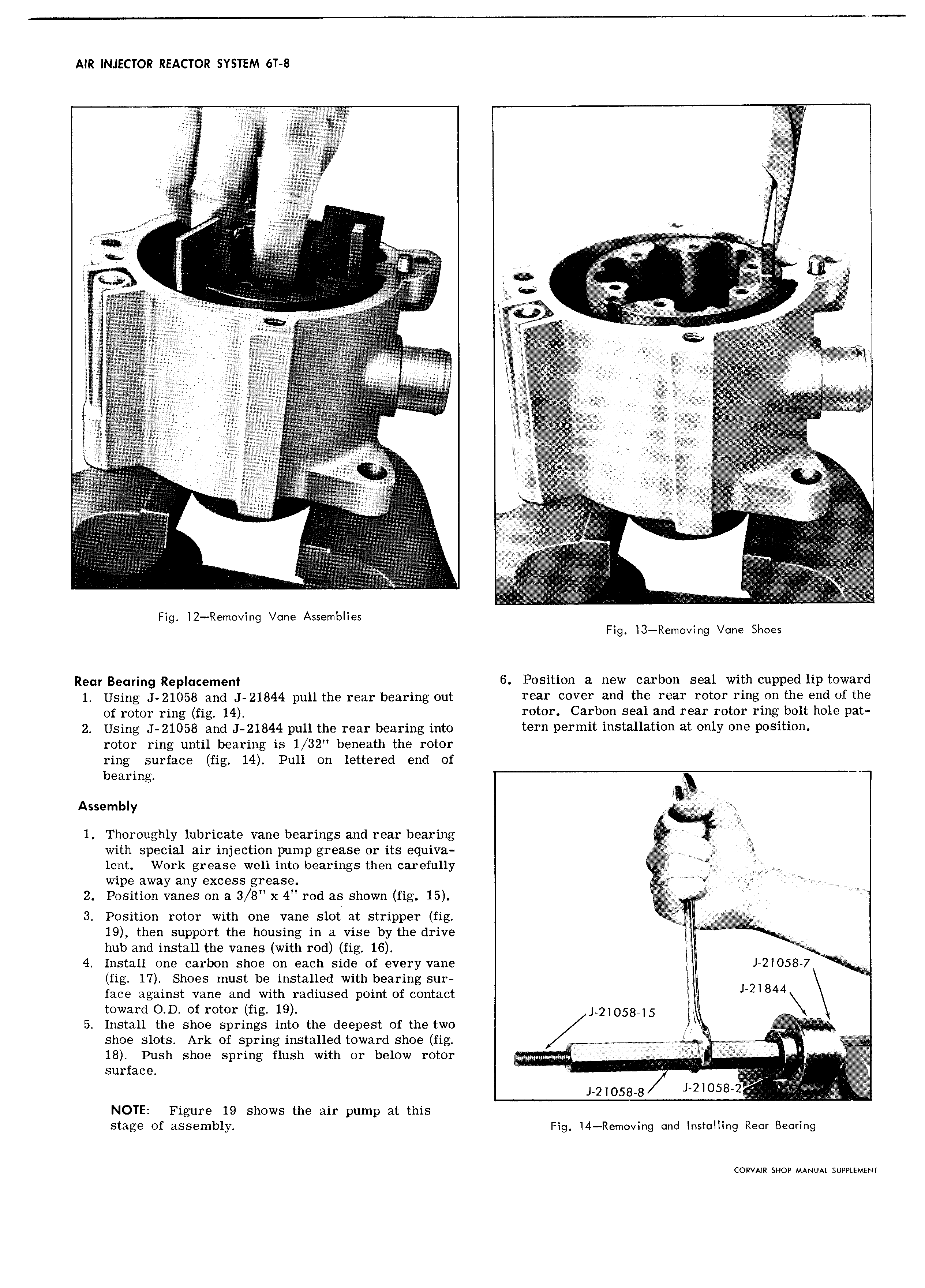
AIR INJECTOR REACTOR SYSTEM 6T 8 S SSSS7 S S S7 SSZ I S SS if YS CS W S V S S 1 v S S S S SS S S S 2S k S 4 S l S S S i S A S S S S S S S i V S SS SS S SS S S S SSS g SSS S i g SSSS SS SS S SSSS S E S TS F 6 SS S S S S f S S i SS S S S S Q V S SS S SSSS S SS SS S S S l e SSSS 1 2 SS SSSS E I TS 1 Si Q SS Y S S SIS Si S S S SSS S S SSS L SSSS S I S S S S S SS S SSSS SS SS SSSS S SSSSS S SS S S I S S SS SS S f f S i SSS S SSSS S SSSSS SSSS S VSSSS S I S SS SSSS S S SS S S S JSSI S S S SSSS SS SS SSSSY SSSS S SS S 1 S22 SSSS v Z SS S SS Q S SS SS S S SS SS S SSSSS SSSSS S S S S SS SS t SSS S S S S S SSSSSSSS SS S SSS S S SS SSSSS SS SS S S SSS SS S SSSSS Z SS S S i S S SSS Sj i SSSSS Si S S S S SSS 1 SSSS SSSS Ei S S S SS SSSS SS Fig l2 Removing Vane Assemblies Fig 3 Removing Vane Shoes Rem gaming Rgplqcgmgnf 6 Position a new carbon seal with cupped lip toward 1 Using J 21058 and J 21844 pull the rear bearing out 1 3I C0V 1 wld th 1 211 rotor NHS OH the Bild of th Of wml ring fig 4 rotor Carbon seal and rear rotor ring bolt hole pat 2 Using J 21058 and J 21844 pull the rear bearing into tern permit installation at only one position rotor ring until bearing is 1 32 beneath the rotor ring surface fig 14 Pull on lettered end of bearing Assembly S S V S 1 Thoroughly lubricate vane bearings and rear bearing fi SSSS with special air injection pump grease or its equiva SS lent Work grease well into bearings then carefully S SSSSS V wipe away any excess grease S SS S p 2 Position vanes on a 3 8 x 4 rod as shown fig 15 E S y SS S S S 3 Position rotor with one vane slot at stripper fig S S g 19 then support the housing in a vise by the drive S S SS SS hub and install the vanes with rod fig 16 S M V 4 Install one carbon shoe on each side of every vane S J 21058 7 SS l S fig 17 Shoes must be installed with bearing sur face against vane and with radiused point of contact J 2l844 toward O D of rotor fig 19 J 2 O58 5 5 Install the shoe springs into the deepest of the two I AS S shoe slots Ark of spring installed toward shoe fig I y S S S SS aa Tj ii 18 Push shoe spring flush with or below rotor SSS SlS S JS SS SSSS S Si surface S S i Q S SS Sr Si J 2 O58 8 iS210s8S2 NOTE Figure 19 shows the air pump at this stage of 21SSBmb1y Fig l4 Remo ing and installing Rear Bearing CORVAIR SHOP MANUAL SUPPLEMENT

 Next
Next