Jeep Parts Wiki | Ford Parts Wiki
Home | Search | Browse | Marketplace | Messages | FAQ | Guest
|
Corvair Chassis Shop Manual Supplement December 1966 |
|
Prev

 Next
Next
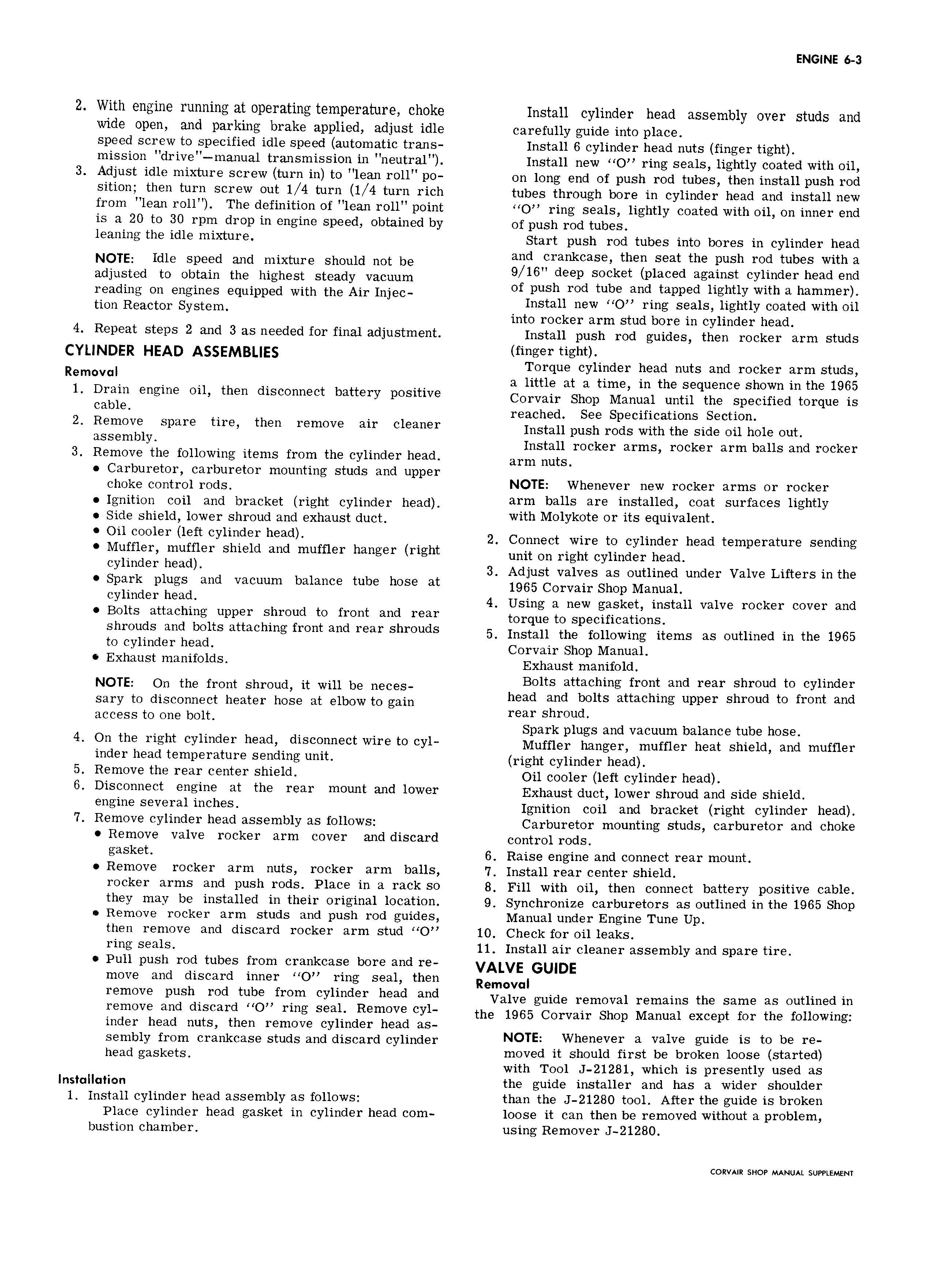
ENGINE 6 3 2 With engine running at operating temperature choke Install cylinder head assembly over studs and wide open and parking brake applied adjust idle carefully guide into place speed screw to specified idle speed automatic trans Install 6 cylinder head nuts finger tight mission drive manual transmission in neutral Install new O ring seals lightly coated with oil 3 Adjust idle mixture screw turn in to lean roll po on long end of push rod tubes then install push rod sition then turn screw out 1 4 turn 1 4 turn rich tubes through bore in cylinder head and install new from lean roll The definition of lean roll point O ring seals lightly coated with oil on inner end is a 20 to 30 rpm drop in engine speed obtained by of push rod tubes leaning the idle mixture Start push rod tubes into bores in cylinder head NOTE ldls spssd and mixture should not bs and vcrankcase then seat the push rod tubes with a sdjustsd ts Obtain the highest steady Vacuum 9 16 deep socket placed against cylinder head end rssdms Os ssslnss squippsd with the Air InjsC of push rod tuheyandt tapped lightly with a hammer tum Rssctsr system I Install new O ring seals lightly coated with oil into rocker arm stud bore in cylinder head 4 Repeat steps 2 and 3 as needed for final adjustment Install push rod guides then rocker arm studs CYLINDER HEAD ASSEMBLIES hhger hghhy Torque cylinder head nuts and rocker arm studs R m v a little at a time in the sequence shown in the 1965 l Drain engine oil then disconnect battery positive Cowan Shop Manual until tho snoolflsd torque ls cable reached See Specifications Section 2 Remove spare tire then remove air cleaner Install hush rods with tho stds oil hols out asssmblr Install rocker arms rocker arm balls and rocker 3 Remove the following items from the cylinder head arm nuts Carburetor carburetor mounting studs and upper Choke COl ltI O1I OdS NOTE Whenever new rocker arms or rocker Ignition coil and bracket right cylinder head arm balls are installed coat surfaces lightly Side shield lower shroud and exhaust duct with Melvkote OY its eqhivelehh Oh eeeler left evhhder heed 2 Connect wire to cylinder head temperature sending Muffler muffler shield and muffler hanger right unit Oh right Cylindgr heath evhheeh heed 3 Adjust valves as outlined under Valve Lifters in the Spark plugs and vacuum balance tube hose at 1965COrVairShOpManua1 evhheeh heee 4 Using a new gasket install valve rocker cover and Bolts attaching upper shroud to front and rear torque to snoolfloattons Shmuds ml belts at hl gf1 0 t and mm shreuds 5 instan tne renewing items as entitned in tne 1965 to cylinder head Corvair Shop Manual Exhaust manifolds Exhaust mautfolll NOTE on the from shroud it will bs nssss Bolts attaching front and rear shroud to cylinder sary ts discsmsct heats hsss at slbsw ts gsm head and bolts attaching upper shroud to front and access to one bolt mer shroud Spark plugs and vacuum balance tube hose 4 On the right cylinder head disconnect wire to cyl Muffler hanger mufflgr heat Shield ahd muffler inder head temperature sending unit right cylinder head 5 Remove the rear center shield 0tj cgglgy 16ft cylinder heady 6 Disconnect engine at the rear mount and lower Exhaust duct lower shroud and side shield Gngine several inches Ignition coil and bracket right cylinder head 7 Remove cylinder head assembly as follows Carburetor mounting studs carburetor and choke Remove valve rocker arm cover and discard control rods gasket 6 Raise engine and connect rear mount Remove rocker arm nuts rocker arm balls 7 Install rear center shield rocker arms and push rods Place in a rack so 8 Fill with oil then connect battery positive cable they may be installed in their original location 9 Synchronize carburetors as outlined in the 1965 Shop Remove rocker arm studs and push rod guides Manual under Engine Tune Up then remove and discard rocker arm stud O 10 Check for oil leaks ring seals 11 Install air cleaner assembly and spare tire Pull push rod tubes from crankcase bore and re VALVE GUIDE move and discard inner O ring seal then Removal remove push me tube from cylinder heed ehd Valve guide removal remains the same as outlined in hemeve end discerd HOU mhg seeh Remove CYL the 1965 Corvair Shop Manual except for the following inder head nuts then remove cylinder head as sembly from crankcase studs and discard cylinder NOTE vvh V r Zi valve aside is ts bs Ye head gaskets moved it should first be broken loose started with Tool J 21281 which is presently used as Instclluiion the guide installer and has a wider shoulder 1 Install cylinder head assembly as follows than the J 21280 tool After the guide is broken Place cylinder head gasket in cylinder head com loose it can then be removed without a problem bustion chamber using Remover J 21280 CORVAIR SHOP MANUAL SUPPLEMENT

 Next
Next