Jeep Parts Wiki | Ford Parts Wiki
Home | Search | Browse | Marketplace | Messages | FAQ | Guest
|
Corvair Chassis Shop Manual Supplement December 1966 |
|
Prev
 Next
Next
545431
545431
123456
123456
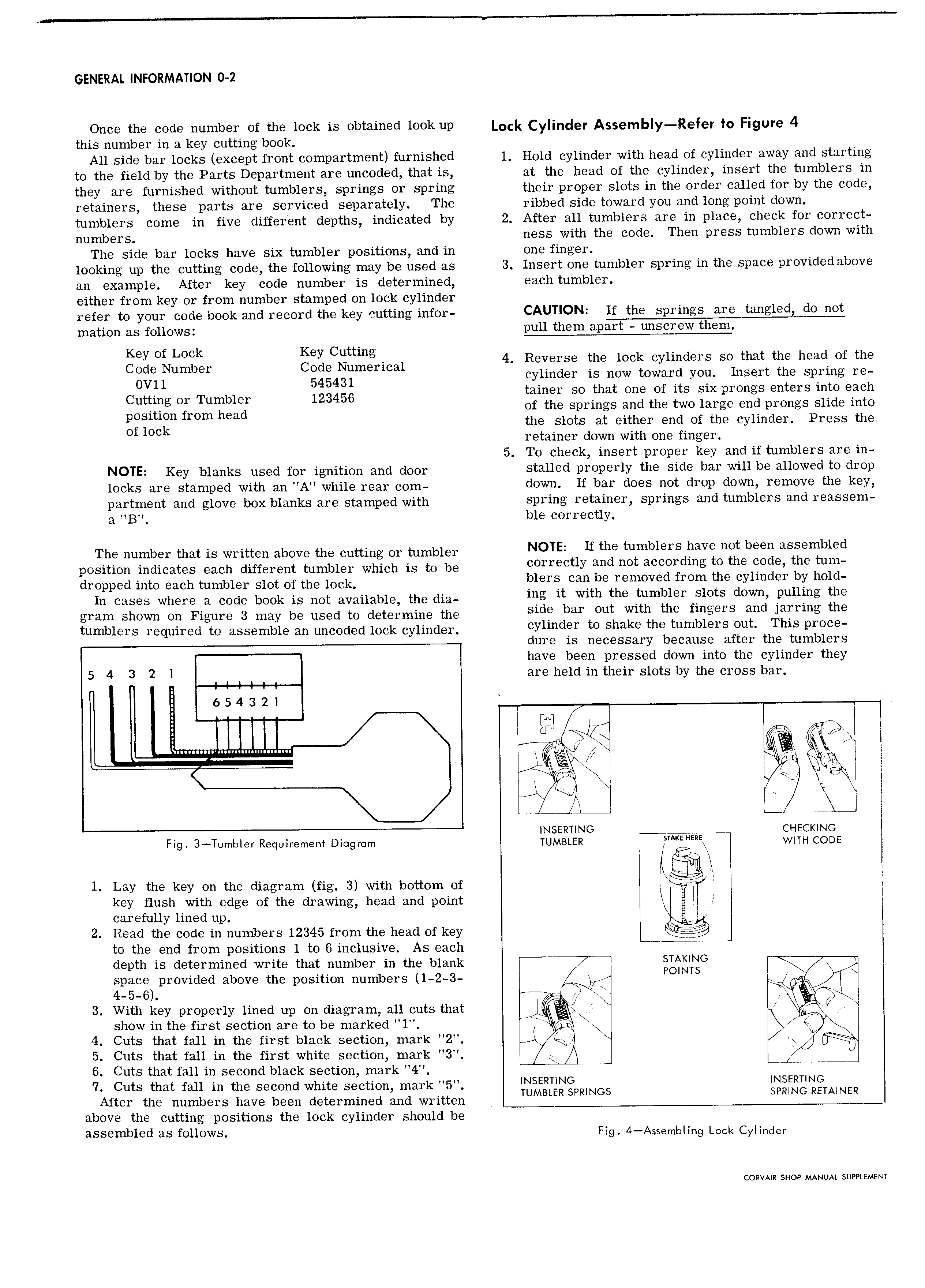
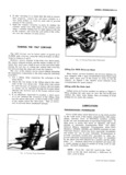
GENERAL INFORMATION 0 2 Once the code number of the lock is obtained look up Lock Cylinder A 9mb y Refoy fg Figure 4 this number in a key cutting book All side bar locks except front compartment furnished 1 Hold cylinder with head of cylinder away and starting to the field by the Parts Department are uncoded that is at the head of the cylinder insert the tumblers in they are furnished without tumblers springs or spring their proper slots in the order called for by the code retainers these parts are serviced separately The ribbed side toward you and long point down tumblers come in five different depths indicated by 2 After all tumblers are in place check for correct numbers ness with the code Then press tumblers down with The side bar locks have six tumbler positions and in one finger looking up the cutting code the following may be used as 3 Insert one tumbler spring in the space provided above an example After key code number is determined each tumbler either from key or from number stamped on lock cylinder refer to your code book and record the key cutting infor CAUTION lf the springs are tangled do not mation as follows pull them apart unscrew them gw Of LOCK Key Cuttmg 4 Reverse the lock cylinders so that the head of the ode Number Code Numerical OV11 545431 cylinder is now toward you Insert the sp ring re Cuttmg Or Tumbler 123456 tainer so that one of its six prongs enters into each position from head of the springs and the two large end prongs slide into Of lock the slots at either end of the cylinder Press the retainer down with one finger 5 To check insert proper key and if tumblers are in NOTE Key blanks used for ignition and door stalled properly the side bar will be allowed to drop locks are stamped with an A while rear com down If ba does not d1 0P down I m0Vc thc Kel partment and glove box blanks are stamped with spring retainer springs and tumblers and reassem a B ble correctly The number that is written above the cutting or tumbler NOTE H the tumblers have net been assembled position indicates each different tumbler which is to be ccrcccuy ccc cct ccccrdicg tc thc cccc the tum dI Opp d mm Each tumbler Slot Of the 1OCk blers can be removed from the cylinder by hold In cases where a code book is not available the nie ing it with the tumbler Slots down pulling the gram shown on Figure 3 may be used to determine the Side bar cut with the fingers and jarring the tumblers required to assemble an uncoded lock cylinder eynnder fe Shake thc tumblers Out This P1 OC dure is necessary because after the tumblers have been pressed down into the cylinder they 5 4 3 2 I are held in their slots by the cross bar 6 5 4 3 2 1 IIIII I n s It I in ug ggpuunnnnunungun i 1 K x J l p 1 new a nc or cl INSERTING HEci No Fig 3 Tumbler Requirement Diogrcim TUMBLER AKE E WITH CODE nd nil l Lay the key on the diagram fig 3 with bottom of I i I key flush with edge of the drawing head and point I carefully lined up I 2 Read the code in numbers 12345 from the head of key I to the end from positions l to 6 inclusive As each L T depth is determined write that number in the blank STAKING 7 space provided above the position numbers 1 2 3 POINTS J 4 5 6 e W ge J 3 With key properly lined up on diagram all cuts that J V show in the first section are to be marked l 4 II I 4 Cuts that fall in the first black section mark 2 x I 5 Cuts that fall in the first white section mark 3 A 6 Cuts that fall in second black section mark 4 7 Cuts that fall in the second white section mark 5 INSERTING INSERTING After the numbers have been determined and written IUMBIER SPRINGS SPRING RETAINER above the cutting positions the lock cylinder should be assembled ELS follows Fig 4 AssembIing Lock Cyiinder CORVAIR SHOP MANUAL SUPPLEMENT