Jeep Parts Wiki | Ford Parts Wiki
Home | Search | Browse | Marketplace | Messages | FAQ | Guest
|
Corvair Chassis Shop Manual Supplement December 1965 |
|
Prev
 Next
Next
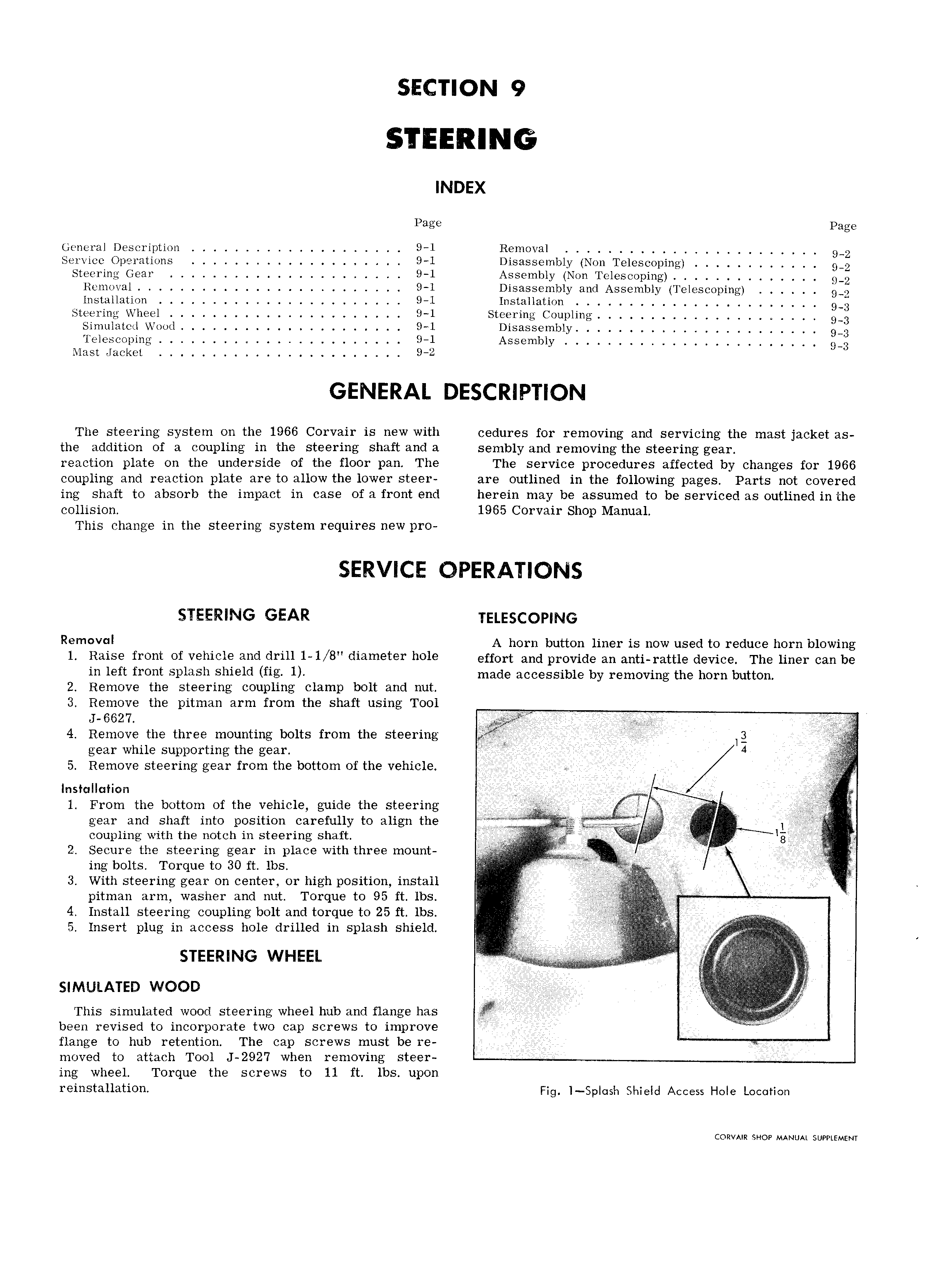
SECTION 9 INDEX Page page General Description 9 1 Removal 9 2 Service Operations 9 l Disassembly Non Telescoping 9 2 Steering Gear 9 1 Assembly Non Tclescoping 9 2 Removal 9 1 Disassembly and Assembly Teleseoping 9 2 7 lnstallation 9 1 lnstallation 9 3 Steering Wheel 9 1 Steering Coupling 9 3 Simulated Wood 9 1 Disassembly 9 3 Telescoping 9 1 Assembly 9 3 Mast Jacket 9 2 GENERAL DESCRIPTION The steering system on the 1966 Corvair is new with cedures for removing and servicing the mast jacket as the addition of a coupling in the steering shaft and a sembly and removing the steering gear reaction plate on the underside of the floor pan The The service procedures affected by changes for 1966 coupling and reaction plate are to allow the lower steer are outlined in the following pages Parts not covered ing shaft to absorb the impact in case of a front end herein may be assumed to be serviced as outlined inthe collision 1965 Corvair Shop Manual This change in the steering system requires new pro SERVICE OPERATIONS STEERING GEAR T 5LE5cgp NG Rem v l A horn button liner is now used to reduce horn blowing l RZUSG f1 0 l of vehicle fmd drill 1 1 8 diameter h0l effort and provide an anti rattle device The liner can be l l ff f1 0 t Sli l 1Sl1 Shlfild fig l made accessible by removing the horn button 2 Remove the steering coupling clamp bolt and nut 3 Remove the pitman arm from the shaft using Tool 4 Remove the three mounting bolts from the steering e lg t gear while supporting the gear I 4 il 5 Remove steering gear from the bottom of the vehicle Installation A 1 From the bottom of the vehicle guide the steering I R iye e gear and shaft into position carefully to align the I I coupling with the notch in steering shaft II l t 4 l Y IV 2 Secure the steering gear in place with three mount I l I I II ing bolts Torque to 30 ft lbs T I I l l I 3 With steering gear on center or high position install V y g pnman arm washer and nut Torque to 95 it 1bs ii i I 4 Install steering coupling bolt and torque to 25 ft lbs I I M i 5 Insert plug in access hole drilled in splash shield in I II II i g STEERING WHEEL I I I I t i I SIMULATED WOOD i g p i This simulated wood steering wheel hub and flange has Y I been revised to incorporate two cap screws to improve IIIII flange to hub retention The cap screws must be re moved to attach Tool J 292 7 when removing steer ing wheel Torque the screws to 11 ft lbs upon I lll l3ll llOYl Fig l Splosl 1 Shield Access Hole Locotion CORVAIR SHOP MANUAL SUPPLEMENT