Jeep Parts Wiki | Ford Parts Wiki
Home | Search | Browse
|
Corvair Chassis Shop Manual Supplement December 1965 |
|
Prev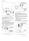
 Next
Next
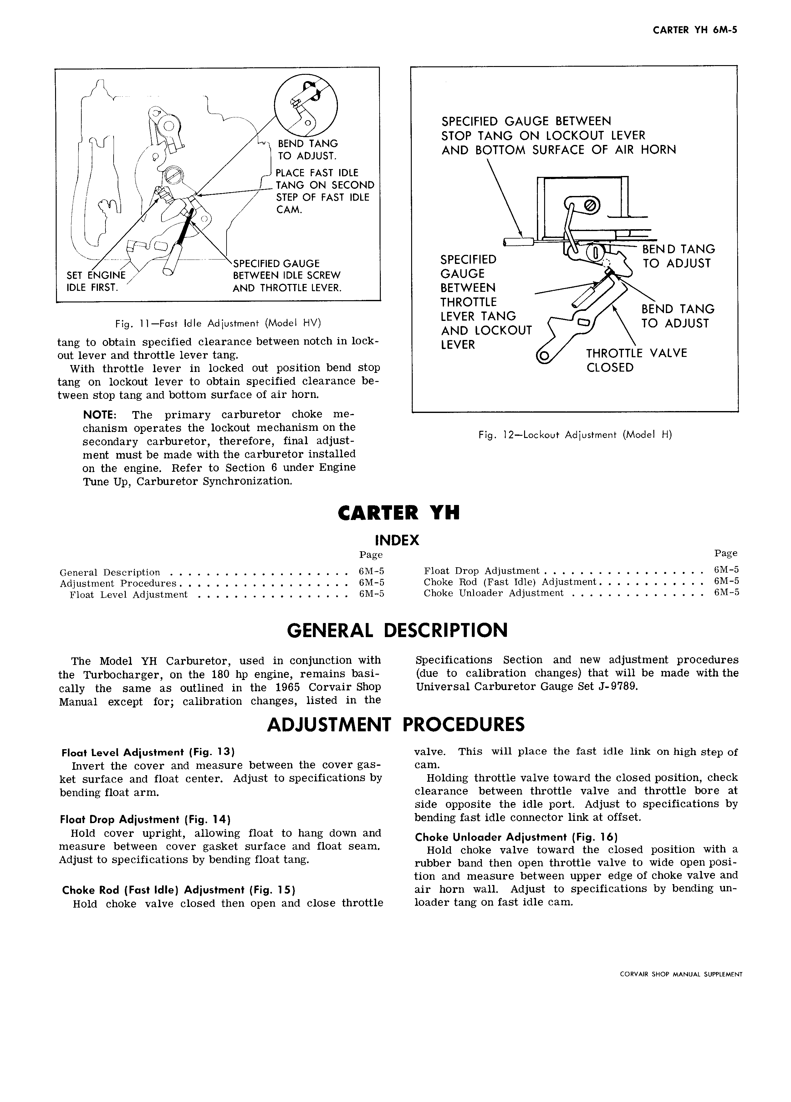
CARTER YI I 6M S A A ks O SPECIFIED GAUGE BETWEEN FU V BEND TANG STOP TANG ON LOCKOUT LEVER j Q TO ADJUST AND BOTTOM SURFACE OF AIR HORN I I PLACE FAST IDLE Z g L TANG ON SECOND 4 STEP OF FAST IDLE I I O CAM 9 A AI5 ii I j x BEND TANG TM D I Eff F4 SPECIFIED GAUGE SPECIFIED TQ ADJUST SET ENGINE BETWEEN IDLE SCREW GAUGE Y IDLE FIRST AND THROTTLE LEVER BETWEEN THROTTLE LEVER TANG I BEND IANG Fig II F I Idle Adjustment Model HV AND LOCKOUT I3 TO ADJUST tang to obtain specified clearance between notch in lock LEVER out lever and throttle lever tang O THROTTLE VALVE With throttle lever in locked out position bend stop QLQSED tang on lockout lever to obtain specified clearance be tween stop tang and bottom surface of air horn NOTE The primary carburetor choke me chanism operates the lockout mechanism on the F I2 L k I secondary carburetor therefore final adjust Ig UI AdI Im I M d HI ment must be made with the carburetor installed on the engine Refer to Section 6 under Engine Tune Up Carburetor Synchronization INDEX Page Page General Description 6M 5 Float Drop Adjustment GM 5 Adjustment Procedures 6M 5 Choke Rod Fast Idle Adjustment 6M 5 Float Level Adjustment 6M 5 Choke Unloader Adjustment 6M 5 The Model YH Carburetor used in conjunction with Specifications Section and new adjustment procedures the Turbocharger on the 180 hp engine remains basi due to calibration changes that will be made with the cally the same as outlined in the 1965 Corvair Shop Universal Carburetor Gauge Set J 9789 Manual except for calibration changes listed in the Floot Level Adjustment Fig 13 valve This will place the fast idle link on high step of Invert the cover and measure between the cover gas cam ket surface and float center Adjust to specifications by Holding throttle valve toward the closed position check bending float arm clearance between throttle valve and throttle bore at side opposite the idle port Adjust to specifications by Float Drop Adjustment Fig 14 bending fast idle connector link at offset Hold cover upright allowmg float to h mg CIOWH 3 Hd Cjwke unjoqder Adjusjmenj Fjg 16 measure between cover gasket surface and float seam Hold choke valve toward the Closed position with a Adlust to spacmcatwns PY bendmg moat tang rubber band then open throttle valve to wide open posi tion and measure between upper edge of choke valve and Choke Rod F st Idle Adjustment Fig 15 air horn wall Adjust to specifications by bending un Hold choke valve closed then open and close throttle loader tang on fast idle cam CORVAIR SHOP MANUAL SUPPLEMENT