Jeep Parts Wiki | Ford Parts Wiki
Home | Search | Browse
Prev
 Next
Next
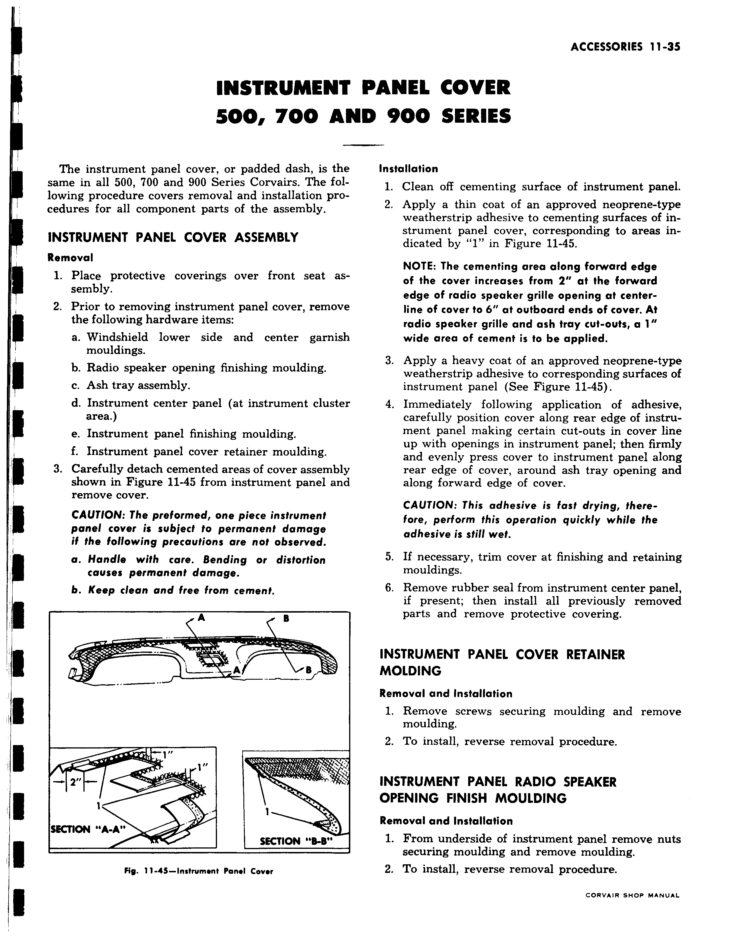
r INSTRUME H1 500 700 AI The instrument panel cover or padded dash is the same in all 500 700 and 900 Series Corvairs The following procedure covers removal and installation procedures for all component parts of the assembly E INSTRUMENT PANEL COVER ASSEMBLY Removal 1 Place protective coverings over front seat assembly 2 Prior to removing instrument panel cover remove E the following hardware items a Windshield lower side and center garnish mouldings E b Radio speaker opening finishing moulding c Ash tray assembly d Instrument center panel at instrument clustei E area e Instrument panel finishing moulding f Instrument panel cover retainer moulding E 3 Carefully detach cemented areas of cover assembly shown in Figure 11 45 from instrument panel anc remove cover CAUTION The preformed one piece instrument panel cover is subject to permanent damage if the following precautions are not observed E a Handle with care Bending or distortion causes permanent damage b Keep clean and free from cement A B A B E Z t t SECTION A A SKTION 8 B Fig 11 45 Insfrvm nf Pan l Covor PANEL COVER ND 900 SERIES Installation 1 Clean off cementing surface of instrument panel 2 Apply a thin coat of an approved neoprene type weatherstrip adhesive to cementing surfaces of instrument panel cover corresponding to areas indicated by 1 in Figure 11 45 NOTE The cementing area along forward edge of the cover increases from 2 at the forward edge of radio speaker grille opening at centerline of cover to 6 at outboard ends of cover At radio speaker grille and ash tray cut outs a 1 wide area of cement is to be applied 3 Apply a heavy coat of an approved neoprene type weatherstrip adhesive to corresponding surfaces of instrument panel See Figure 11 45 4 Immediately following application of adhesive carefully position cover along rear edge of instrument panel making certain cut outs in cover line up with openings in instrument panel then firmly and evenly press cover to instrument panel along rear edge of cover around ash tray opening and along forward edge of cover CAUTION This adhesive is fast drying therefore perform this operation quickly while the adhesive is still wet 5 If necessary trim cover at finishing and retaining mouldings 6 Remove rubber seal from instrument center panel if present then install all previously removed parts and remove protective covering INSTRUMENT PANEL COVER RETAINER MOLDING Removal and Installation 1 Remove screws securing moulding and remove moulding 2 To install reverse removal procedure INSTRUMENT PANEL RADIO SPEAKER OPENING FINISH MOULDING Removal and Installation 1 From underside of instrument panel remove nuts securing moulding and remove moulding 2 To install reverse removal procedure