Jeep Parts Wiki | Ford Parts Wiki
Home | Search | Browse
Prev
 Next
Next
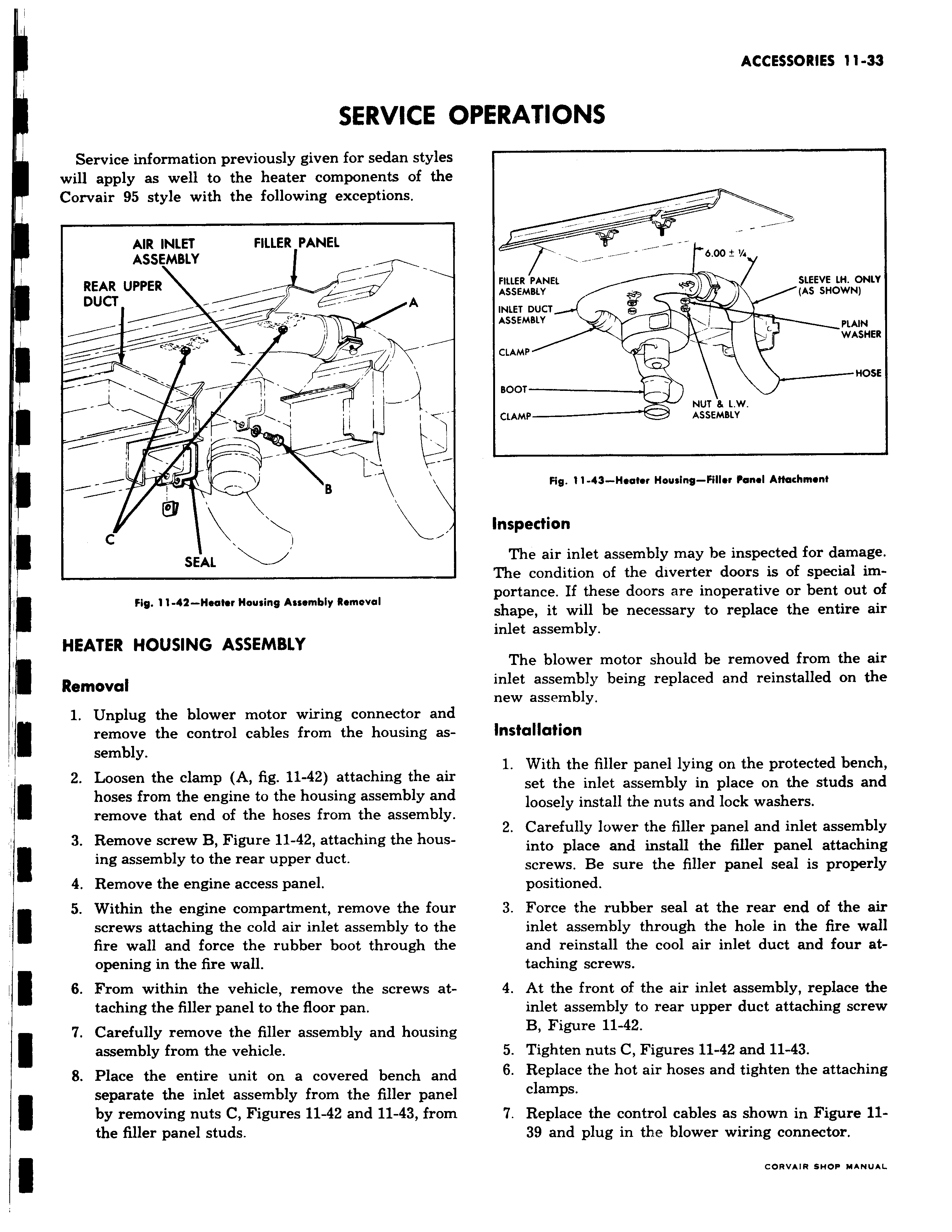
SERVICE I I Service information previously given for sedan styles will apply as well to the heater components of the Corvair 95 style with the following exceptions AIR INLET FILLER PANEL ASSEMBLY REAR UPPER DUCT A i T I l i w B C I SEAL Fig 11 44 Heater Housing Assembly Removal HEATER HOUSING ASSEMBLY I Removal 1 Unplug the blower motor wiring connector and remove the control cables from the housing assembly 2 Loosen the clamp A fig 11 42 attaching the au hoses from the engine to the housing assembly and remove that end of the hoses from the assembly 3 Remove screw B Figure 11 42 attaching the housing assembly to the rear upper duct 4 Remove the engine access panel 5 Within the engine compartment remove the foui screws attaching the cold air inlet assembly to the fire wall and force the rubber boot through the opening in the fire wall 6 From within the vehicle remove the screws at taching the filler panel to the floor pan 7 Carefully remove the filler assembly and housing assembly from the vehicle 8 Place the entire unit on a covered bench anc separate the inlet assembly from the filler pane by removing nuts C Figures 11 42 and 11 43 fron the filler panel studs 3PERATIONS 6 00 1a FILLER PANEL SLEEVE LH ONLY ASSEMBLY AS SHOWN INLET DUCT ASSEMBLY PLAIN WASHER CLAMP HOSE BOOT NUT L W CLAMP ASSEMBLY Fig 11 43 Heater Housing Filler Panel AHachmenf Inspection The air inlet assembly may be inspected for damage The condition of the diverter doors is of special importance If these doors are inoperative or bent out of shape it will be necessary to replace the entire air inlet assembly The blower motor should be removed from the air inlet assembly being replaced and reinstalled on the new assembly Installation 1 With the filler panel lying on the protected bench set the inlet assembly in place on the studs and loosely install the nuts and lock washers 2 Carefully lower the filler panel and inlet assembly into place and install the filler panel attaching screws Be sure the filler panel seal is properly positioned 3 Force the rubber seal at the rear end of the air inlet assembly through the hole in the fire wall and reinstall the cool air inlet duct and four attaching screws 4 At the front of the air inlet assembly replace the inlet assembly to rear upper duct attaching screw B Figure 11 42 5 Tighten nuts C Figures 11 42 and 11 43 6 Replace the hot air hoses and tighten the attaching clamps 7 Replace the control cables as shown in Figure 1139 and plug in the blower wiring connector