Jeep Parts Wiki | Ford Parts Wiki
Home | Search | Browse
Prev
 Next
Next
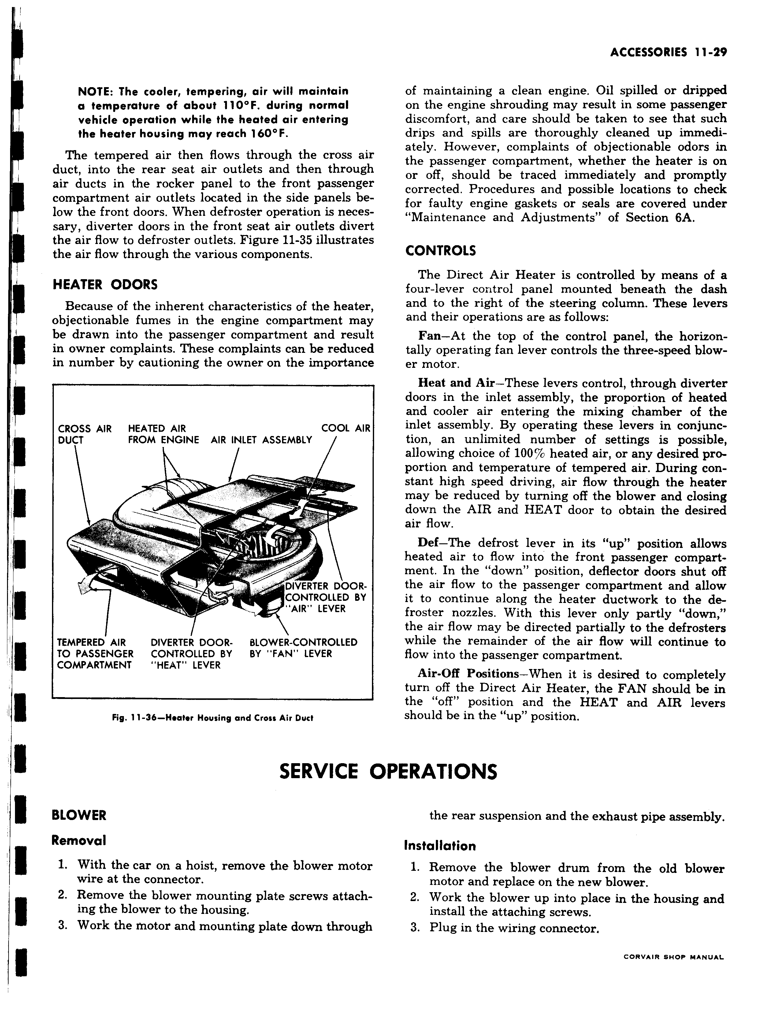
r II NOTE The cooler tempering air will maintain a temperature of about 110 F during normal vehicle operation while the heated air entering the heater housing may reach 160 F The tempered air then flows through the cross aii duct into the rear seat air outlets and then througr air ducts in the rocker panel to the front passengei compartment air outlets located in the side panels be low the front doors When defroster operation is neces sary diverter doors in the front seat air outlets diveri the air flow to defroster outlets Figure 11 35 illustrate the air flow through the various components HEATER ODORS Because of the inherent characteristics of the heater objectionable fumes in the engine compartment may be drawn into the passenger compartment and resuh in owner complaints These complaints can be reducec in number by cautioning the owner on the importancE CROSS AIR HEATED AIR COOL AIR DUCT FROM ENGINE AIR INLET ASSEMBLY f 1 r1r j DIVER ER DOORCONTROLLED BY AIR LEVER TEMPERED AIR DIVERTER DOOR BLOWER CONTROLLED I TO PASSENGER CONTROLLED BY BY FAN LEVER COMPARTMENT HEAT LEVER Fig 11 36 Heater Housing and Cross Air Duct SERVICE BLOWER Removal 1 With the car on a hoist remove the blower motor wire at the connector 2 Remove the blower mounting plate screws attaching the blower to the housing 3 Work the motor and mounting plate down through r of maintaining a clean engine Oil spilled or dripped on the engine shrouding may result in some passenger discomfort and care should be taken to see that such drips and spills are thoroughly cleaned up immediately However complaints of objectionable odors in the passenger compartment whether the heater is on or off should be traced immediately and promptly corrected Procedures and possible locations to check for faulty engine gaskets or seals are covered under Maintenance and Adjustments of Section 6A CONTROLS The Direct Air Heater is controlled by means of a four lever control panel mounted beneath the dash and to the right of the steering column These levers and their operations are as follows Fan At the top of the control panel the horizon tally operating fan lever controls the three speed blower motor Heat and Air These levers control through diverter doors in the inlet assembly the proportion of heated and cooler air entering the mixing chamber of the inlet assembly By operating these levers in conjunction an unlimited number of settings is possible allowing choice of 100 heated air or any desired proportion and temperature of tempered air During constant high speed driving air flow through the heater may be reduced by turning off the blower and closing down the AIR and HEAT door to obtain the desired air flow Def The defrost lever in its up position allows heated air to flow into the front passenger compartment In the down position deflector doors shut off the air flow to the passenger compartment and allow it to continue along the heater ductwork to the de froster nozzles With this lever only partly down I the air flow may be directed partially to the defrosters while the remainder of the air flow will continue to flow into the passenger compartment Air Off Positions When it is desired to completely j turn off the Direct Air Heater the FAN should be in the off position and the HEAT and AIR levers should be in the up position DPERATIONS the rear suspension and the exhaust pipe assembly Installation 1 Remove the blower drum from the old blower motor and replace on the new blower 2 Work the blower up into place in the housing and install the attaching screws 3 Plug in the wiring connector