Jeep Parts Wiki | Ford Parts Wiki
Home | Search | Browse
Prev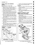
 Next
Next
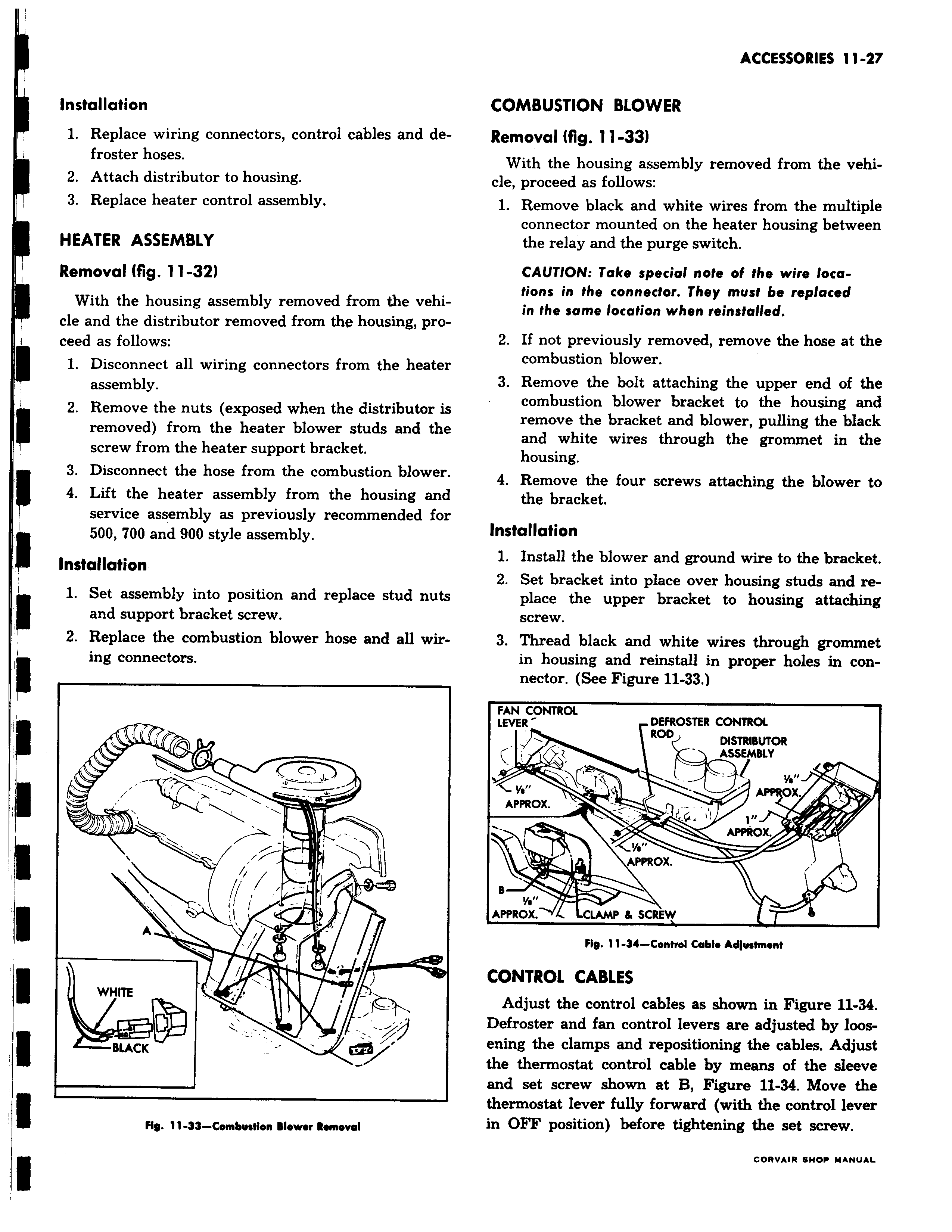
r I Installation 1 Replace wiring connectors control cables and defroster hoses 1 2 Attach distributor to housing 3 Replace heater control assembly HEATER ASSEMBLY Removal fig 11 32 With the housing assembly removed from the vehicle and the distributor removed from the housing proceed as follows 1 Disconnect all wiring connectors from the heater assembly 2 Remove the nuts exposed when the distributor is removed from the heater blower studs and the screw from the heater support bracket 3 Disconnect the hose from the combustion blower 4 Lift the heater assembly from the housing and service assembly as previously recommended for 500 700 and 900 style assembly Installation 1 Set assembly into position and replace stud nuts and support bracket screw 2 Replace the combustion blower hose and all wiring connectors v i n i l vl A WHITE BLACK Fly 11 33 Combustion Blower Removal COMBUSTION BLOWER Removal fig 11 33 With the housing assembly removed from the vehicle proceed as follows 1 Remove black and white wires from the multiple connector mounted on the heater housing between the relay and the purge switch CAUTION Take special note of the wire locations in the connector They must be replaced in the same location when reinstalled 2 If not previously removed remove the hose at the combustion blower 3 Remove the bolt attaching the upper end of the combustion blower bracket to the housing and remove the bracket and blower pulling the black and white wires through the grommet in the housing 4 Remove the four screws attaching the blower to the bracket Installation 1 Install the blower and ground wire to the bracket 2 Set bracket into place over housing studs and replace the upper bracket to housing attaching screw 3 Thread black and white wires through grommet in housing and reinstall in proper holes in connector See Figure 11 33 FAN CONTROL LEVER DEFROSTER CONTROL ROD DISTRIBUTOR r ASSEMBLY A ox APPROx APPROX Y APPROX B a APPROX CLAMP SCREW 8 Fig 11 34 Control Cable Adjustment CONTROL CABLES Adjust the control cables as shown in Figure 11 34 Defroster and fan control levers are adjusted by loosening the clamps and repositioning the cables Adjust the thermostat control cable by means of the sleeve and set screw shown at B Figure 11 34 Move the thermostat lever fully forward with the control lever in OFF position before tightening the set screw GORV IR SWOP Y Nll L