Jeep Parts Wiki | Ford Parts Wiki
Home | Search | Browse
Prev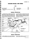
 Next
Next
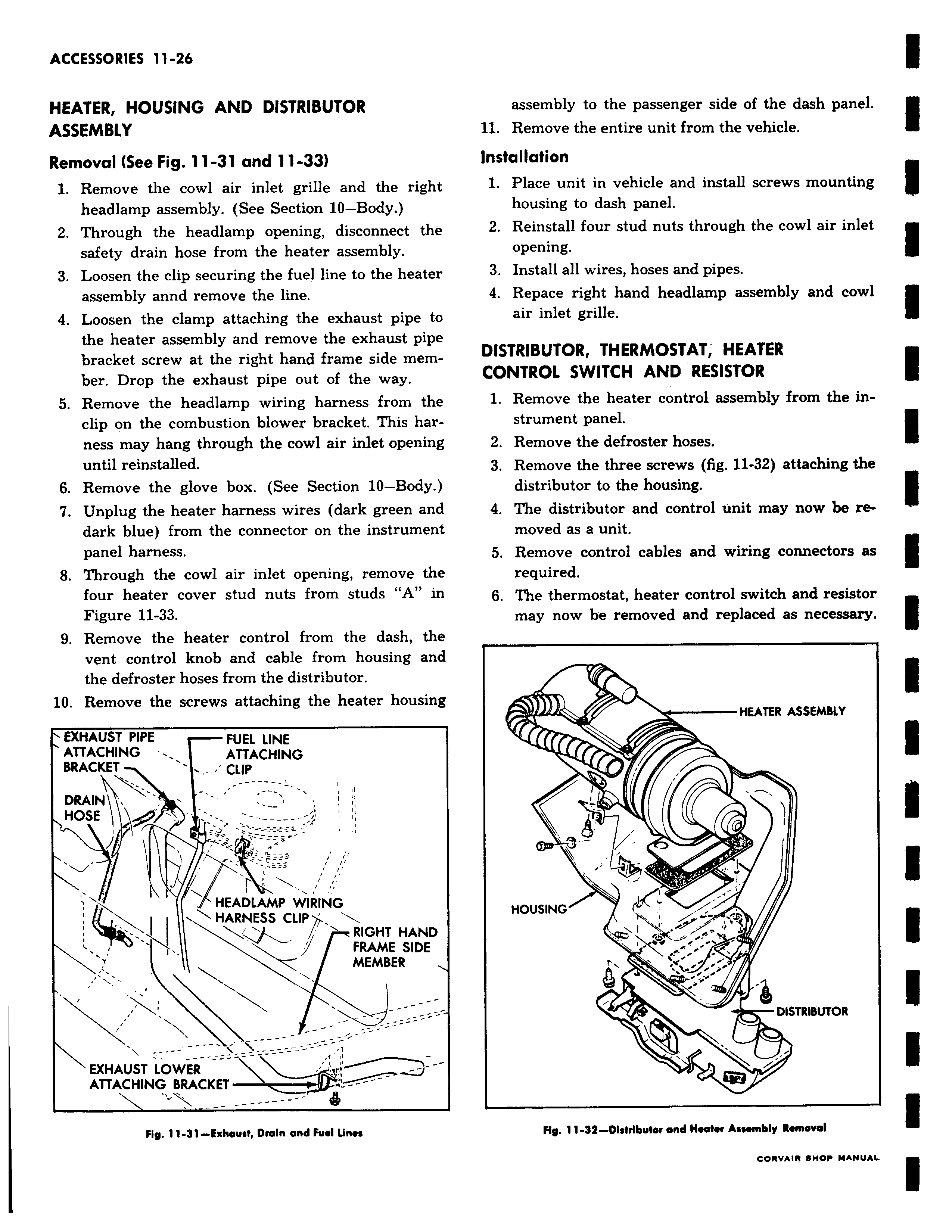
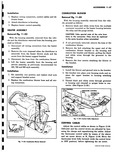
HEATER HOUSING AND DISTRIBUTOR ASSEMBLY Removal See Fig 11 31 and 11 33 1 Remove the cowl air inlet grille and the right headlamp assembly See Section 10 Body 2 Through the headlamp opening disconnect the safety drain hose from the heater assembly 3 Loosen the clip securing the fuel line to the heater assembly annd remove the line 4 Loosen the clamp attaching the exhaust pipe to the heater assembly and remove the exhaust pipe bracket screw at the right hand frame side member Drop the exhaust pipe out of the way 5 Remove the headlamp wiring harness from the clip on the combustion blower bracket This harness may hang through the cowl air inlet opening until reinstalled 6 Remove the glove box See Section 10 Body 7 Unplug the heater harness wires dark green and dark blue from the connector on the instrument panel harness 8 Through the cowl air inlet opening remove the four heater cover stud nuts from studs A in Figure 11 33 9 Remove the heater control from the dash the vent control knob and cable from housing and the defroster hoses from the distributor 10 Remove the screws attaching the heater housing EXHAUST PIPE FUEL LINE ATTACHING ATTACHING BRACKET CLIP DRAIN HOSE HEADLAMP WIRING HARNESS CLIP RIGHT HAND FRAME SIDE MEMBER EXHAUST LOWER ATTACHING BRACKET w iiy 11 31 Exhaust Drain and Fuel Unes assembly to the passenger side of the dash panel 11 Remove the entire unit from the vehicle Installation 1 Place unit in vehicle and install screws mounting housing to dash panel 2 Reinstall four stud nuts through the cowl air inlet opening 3 Install all wires hoses and pipes 4 Repace right hand headlamp assembly and cowl air inlet grille DISTRIBUTOR THERMOSTAT HEATER CONTROL SWITCH AND RESISTOR 1 Remove the heater control assembly from the instrument panel 2 Remove the defroster hoses 3 Remove the three screws fig 11 32 attaching the distributor to the housing 4 The distributor and control unit may now be removed as a unit 5 Remove control cables and wiring connectors as required 6 The thermostat heater control switch and resistor may now be removed and replaced as necessary HEATER ASSEMBLY I i HOUSING r y DISTRIBUTOR v Hy 11 32 Distributor and Hector Assembly Removal CORVAIR SHOP MANUAL