Jeep Parts Wiki | Ford Parts Wiki
Home | Search | Browse
Prev
 Next
Next
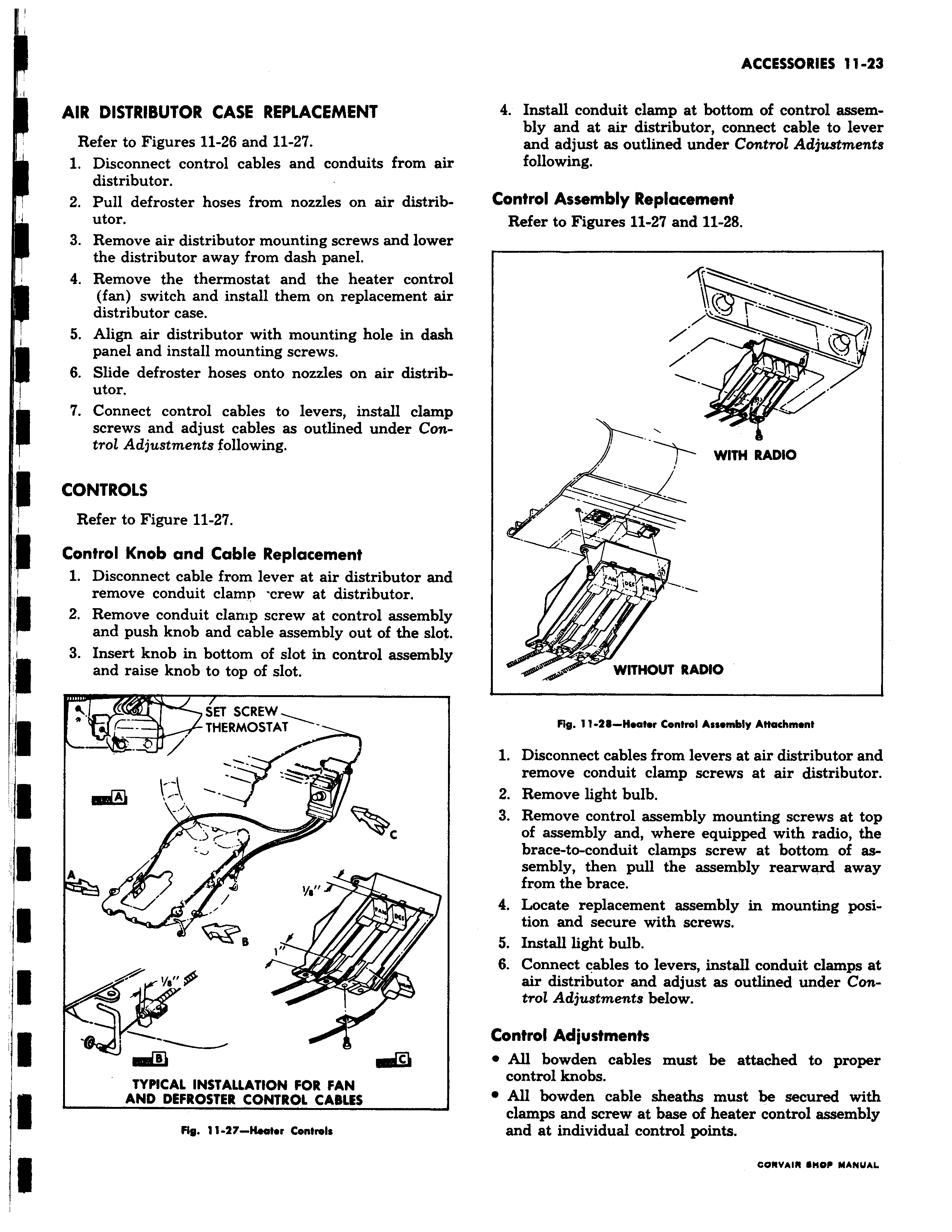
r II AIR DISTRIBUTOR CASE REPLACEMENT Refer to Figures 11 26 and 11 27 1 Disconnect control cables and conduits from sir distributor 2 Pull defroster hoses from nozzles on air distributor 3 Remove air distributor mounting screws and lower the distributor away from dash panel 4 Remove the thermostat and the heater control fan switch and install them on replacement air distributor case 5 Align air distributor with mounting hole in dash panel and install mounting screws 6 Slide defroster hoses onto nozzles on air distributor 7 Connect control cables to levers install clamp screws and adjust cables as outlined under Control Adjustments following CONTROLS Refer to Figure 11 27 Control Knob and Cable Replacement 1 Disconnect cable from lever at air distributor and remove conduit clamp crew at distributor 2 Remove conduit clamp screw at control assembly and push knob and cable assembly out of the slot 3 Insert knob in bottom of slot in control assembly and raise knob to top of slot SET SCREW THERMOSTAT w W c A J I 0 41 d TYPICAL INSTALLATION FOR FAN AND DEFROSTER CONTROL CABLES H8 11 27 Hoater Controls 4 Install conduit clamp at bottom of control assembly and at air distributor connect cable to lever and adjust as outlined under Control Adjustments following Control Assembly Replacement Refer to Figures 11 27 and 11 28 w WITH RADIO F l W yoci r w w WITHOUT RADIO Fig 11 28 Hoafor Control Assombly Affaehmonf 1 Disconnect cables from levers at air distributor and remove conduit clamp screws at air distributor 2 Remove light bulb 3 Remove control assembly mounting screws at top of assembly and where equipped with radio the brace to conduit clamps screw at bottom of as sembly then pull the assembly rearward away from the brace 4 Locate replacement assembly in mounting position and secure with screws 5 Install light bulb 6 Connect cables to levers install conduit clamps at air distributor and adjust as outlined under Control Adjustments below Control Adjustments All bowden cables must be attached to proper control knobs All bowden cable sheaths must be secured with clamps and screw at base of heater control assembly and at individual control points