Jeep Parts Wiki | Ford Parts Wiki
Home | Search | Browse | Marketplace | Messages | FAQ | Guest
Prev

 Next
Next
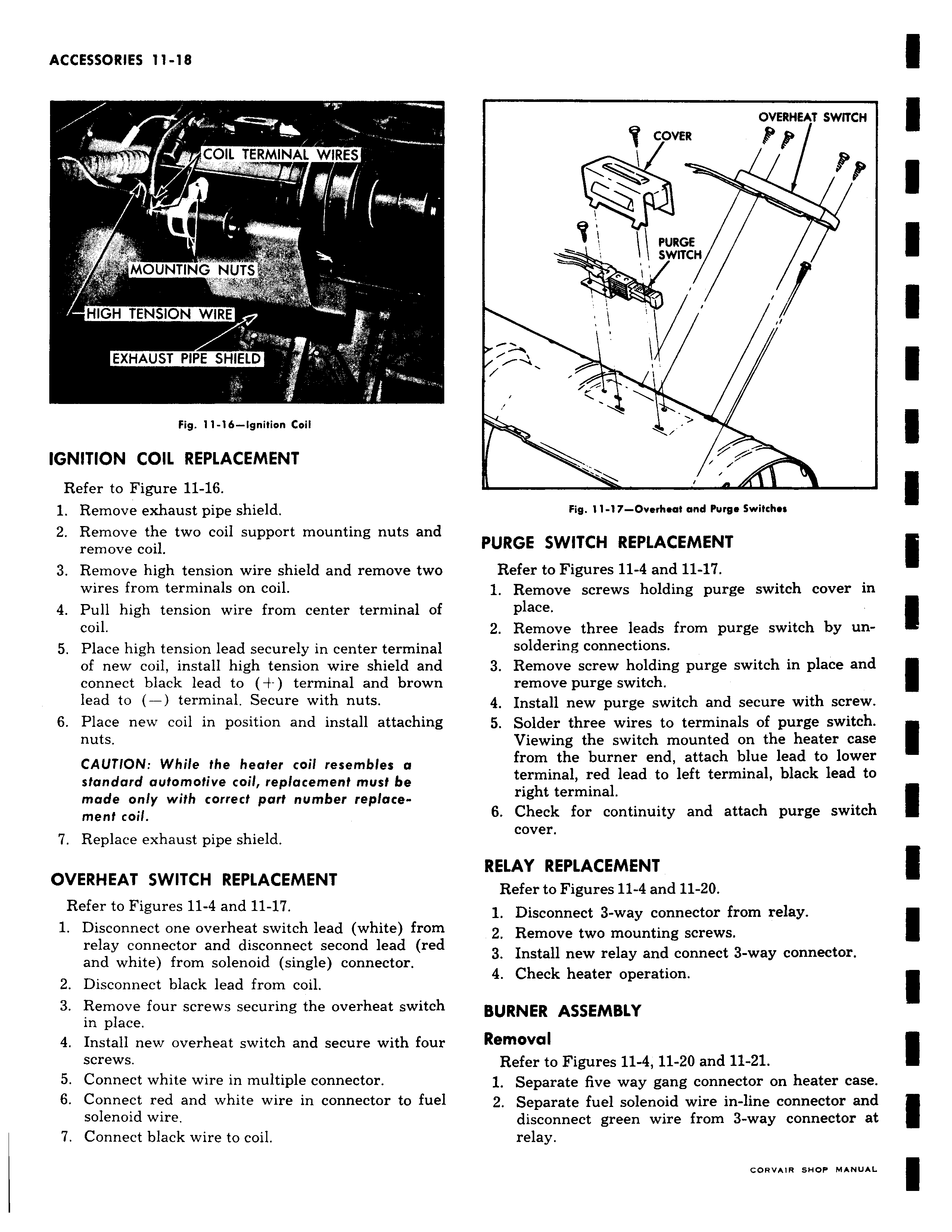
COIL TERMINAL WIRES r r r MOUNTING NUTS HIGH TENSION WIRE EXHAUST PIPE SHIELD Fig 11 16 Ignition Coil IGNITION COIL REPLACEMENT Refer to Figure 11 16 1 Remove exhaust pipe shield 2 Remove the two coil support mounting nuts and remove coil 3 Remove high tension wire shield and remove two wires from terminals on coil 4 Pull high tension wire from center terminal of coil 5 Place high tension lead securely in center terminal of new coil install high tension wire shield and connect black lead to terminal and brown lead to terminal Secure with nuts 6 Place new coil in position and install attaching nuts CAUTION While the heater coil resembles a standard automotive coil replacement must be mode only with correct part number replacement coil 7 Replace exhaust pipe shield OVERHEAT SWITCH REPLACEMENT Refer to Figures 11 4 and 11 17 1 Disconnect one overheat switch lead white from relay connector and disconnect second lead red and white from solenoid single connector 2 Disconnect black lead from coil 3 Remove four screws securing the overheat switch in place 4 Install new overheat switch and secure with four screws 5 Connect white wire in multiple connector 6 Connect red and white wire in connector to fuel solenoid wire 7 Connect black wire to coil OVERHEAT SWITCH COVER 1 I I PURGE SWITCH I I Fig 11 17 Overheat and Purge Switches PURGE SWITCH REPLACEMENT Refer to Figures 11 4 and 11 17 1 Remove screws holding purge switch cover in place 2 Remove three leads from purge switch by unsoldering connections 3 Remove screw holding purge switch in place and remove purge switch 4 Install new purge switch and secure with screw 5 Solder three wires to terminals of purge switch Viewing the switch mounted on the heater case from the burner end attach blue lead to lower terminal red lead to left terminal black lead to right terminal 6 Check for continuity and attach purge switch cover RELAY REPLACEMENT Refer to Figures 11 4 and 11 20 1 Disconnect 3 way connector from relay 2 Remove two mounting screws 3 Install new relay and connect 3 way connector 4 Check heater operation BURNER ASSEMBLY Removal Refer to Figures 11 4 11 20 and 11 21 1 Separate five way gang connector on heater case 2 Separate fuel solenoid wire in line connector and disconnect green wire from 3 way connector at relay

 Next
Next