Jeep Parts Wiki | Ford Parts Wiki
Home | Search | Browse
Prev

 Next
Next
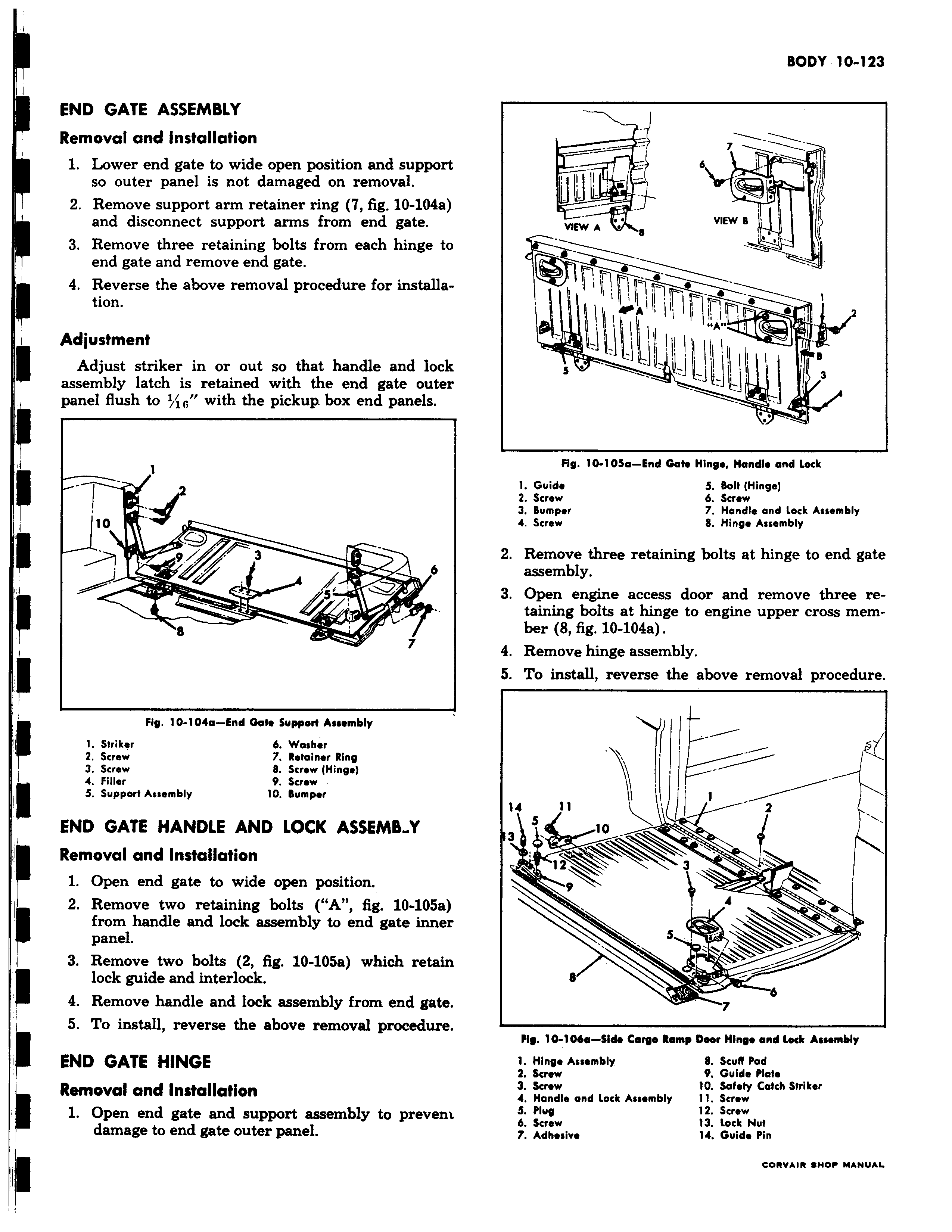
END GATE ASSEMBLY Removal and Installation 1 Lower end gate to wide open position and support so outer panel is not damaged on removal 2 Remove support arm retainer ring 7 fig 10 104a and disconnect support arms from end gate 3 Remove three retaining bolts from each hinge to end gate and remove end gate 4 Reverse the above removal procedure for installation Adjustment I Adjust striker in or out so that handle and lock assembly latch is retained with the end gate outer panel flush to Iii with the pickup box end panels 1 10 3 1 a s 8 7 Fig 10 104a End Gate Support Assembly 1 Striker b Washer 2 Screw 7 Retainer Ring 3 Screw 8 Screw Hinge 4 filler 9 Screw S Support Assembly 10 Bumper END GATE HANDLE AND LOCK ASSEMB Y Removal and Installation 1 Open end gate to wide open position 2 Remove two retaining bolts A fig 10 105a from handle and lock assembly to end gate inner panel 3 Remove two bolts 2 fig 10 1O5a which retain lock guide and interlock 4 Remove handle and lock assembly from end gate 5 To install reverse the above removal procedure END GATE HINGE Removal and Installation 1 Open end gate and support assembly to prevent damage to end gate outer panel W b w M VIEW VIEW B I 1 I IrA e Fig 10 105a End Gate Hinge Handle and Lock 1 Guide 5 Bolt Hinge 2 Screw 6 Screw 3 Bumper 7 Handle and Lock Assembly 4 Screw 8 Hinge Assembly 2 Remove three retaining bolts at hinge to end gate assembly 3 Open engine access door and remove three retaining bolts at hinge to engine upper cross member 8 fig 10 104a 4 Remove hinge assembly 5 To install reverse the above removal procedure 14 11 2 S 3 1 3 9 4 3 Fig 10 106a Side Cargo Romp Deer Hinge and Lock Assembly 1 Hinge Assembly 8 Scuff Pad 2 Screw 9 Guide Plate 3 Screw 10 Safety Catch Striker 4 Handle and Lock Assembly 11 Screw S Plug 12 Screw b Screw 13 Lock Nut 7 Adhesive 14 Guide Pin

 Next
Next