Jeep Parts Wiki | Ford Parts Wiki
Home | Search | Browse
Prev
 Next
Next
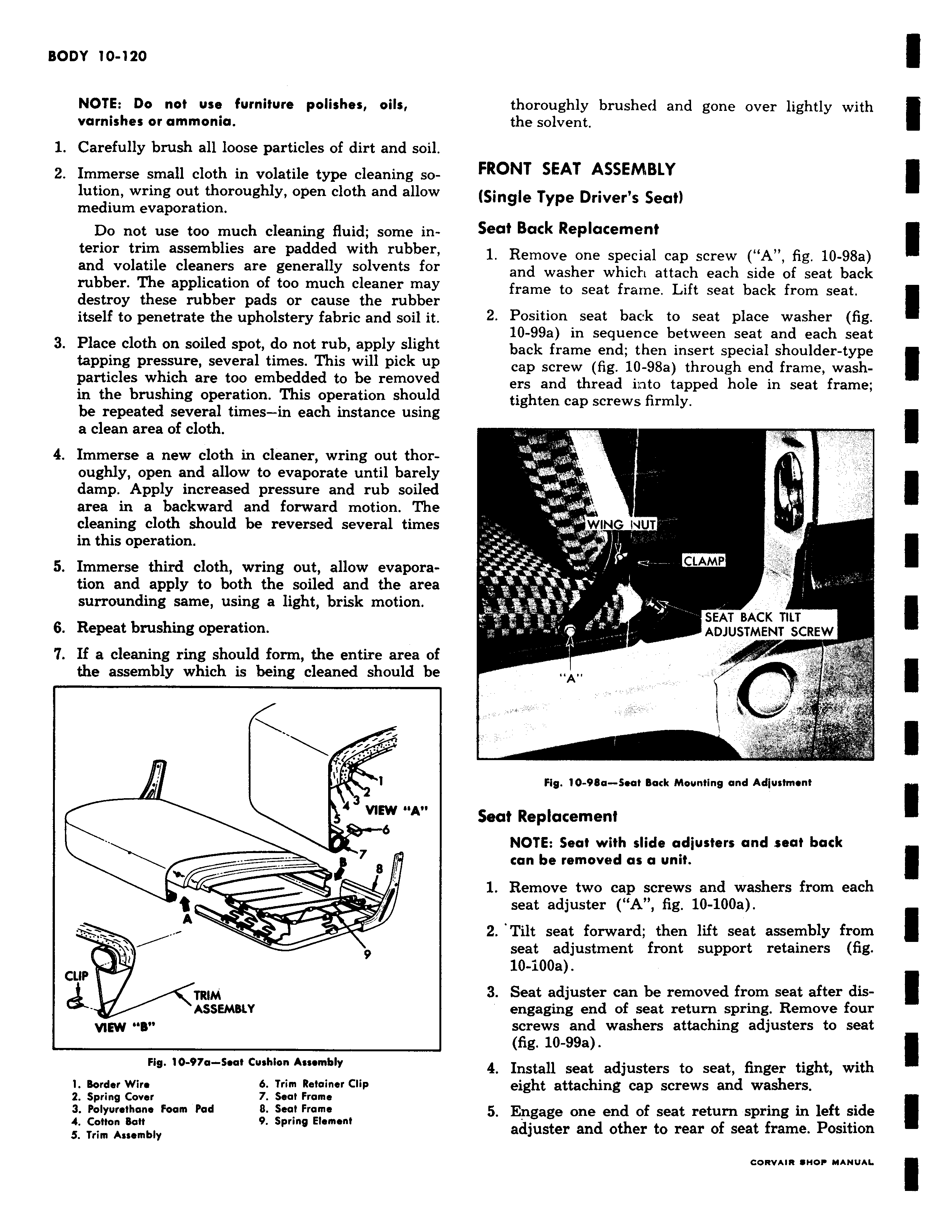
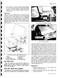
NOTE Do not use furniture polishes oils varnishes or ammonia 1 Carefully brush all loose particles of dirt and soil 2 Immerse small cloth in volatile type cleaning solution wring out thoroughly open cloth and allow medium evaporation Do not use too much cleaning fluid some interior trim assemblies are padded with rubber and volatile cleaners are generally solvents for rubber The application of too much cleaner may destroy these rubber pads or cause the rubber itself to penetrate the upholstery fabric and soil it 3 Place cloth on soiled spot do not rub apply slight tapping pressure several times This will pick up particles which are too embedded to be removed in the brushing operation This operation should be repeated several times in each instance using a clean area of cloth 4 Immerse a new cloth in cleaner wring out thoroughly open and allow to evaporate until barely damp Apply increased pressure and rub soiled area in a backward and forward motion The cleaning cloth should be reversed several times in this operation 5 Immerse third cloth wring out allow evaporation and apply to both the soiled and the area surrounding same using a light brisk motion 6 Repeat brushing operation 7 If a cleaning ring should form the entire area of the assembly which is being cleaned should be i i li 1 4 3 VI 7 8 A 9 CLIP TRIM ASSEMBLY VIEW B Fig 10 97a Seat Cushion Assembly 1 Border Wire 6 Trim Retainer Clip 2 Spring Cover 7 Seat Frame 3 Polyurethane Foam Pad 0 Seat Frame 4 Cotton Batf 9 Spring Element S Trim Assembly thoroughly brushed and gone over lightly with the solvent FRONT SEAT ASSEMBLY Single Type Driver s Seat Seat Back Replacement 1 Remove one special cap screw A fig 10 98a and washer which attach each side of seat back frame to seat frame Lift seat back from seat 2 Position seat back to seat place washer fig 10 99a in sequence between seat and each seat back frame end then insert special shoulder type cap screw fig 10 98a through end frame washers and thread into tapped hole in seat frame tighten cap screws firmly T WING 4UT r t CLAMP SEAT BACK TILT ADJUSTMENT SCREW I A Fig 10 98a Seat Back Mounting and Adjustment Seat Replacement NOTE Seat with slide adjusters and seat back can be removed as a unit 1 Remove two cap screws and washers from each seat adjuster A fig 10 100a 2 Tilt seat forward then lift seat assembly from seat adjustment front support retainers fig 10 i00a 3 Seat adjuster can be removed from seat after disengaging end of seat return spring Remove four screws and washers attaching adjusters to seat fig 10 99a 4 Install seat adjusters to seat finger tight with eight attaching cap screws and washers 5 Engage one end of seat return spring in left side adjuster and other to rear of seat frame Position