Jeep Parts Wiki | Ford Parts Wiki
Home | Search | Browse | Marketplace | Messages | FAQ | Guest
Prev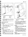
 Next
Next
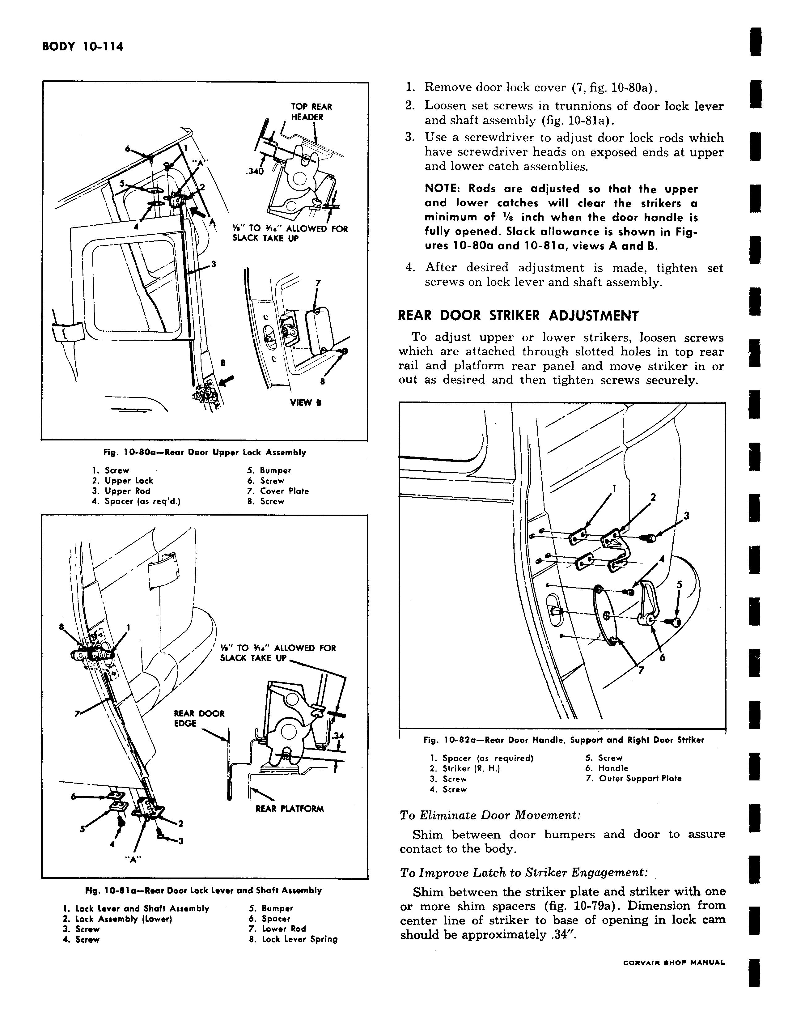
TOP REAR HEADER b t v A y 340 A TO i ALLOWED FOR w I SLACK TAKE UP 3 i I 77 B VIEW s Fig 10 80a Rear Door Upper Lock Assembly 1 Screw 5 Bumper 2 Upper Lock 6 Screw 3 Upper Rod 7 Cover Plate 4 Spacer as req d 8 Screw v C t ys TO 15s ALLOWED FOR SLACK TAKE UP 1te 7 REAR DOOR EDGE O I v v 34 REAR PLATFORM s f 4 3 A Fig 10 81a Rear Door Lock Lever and Shaft Assembly 1 Lock Lever and Shaft Assembly 5 Bumper 2 Lock Assembly Lower b Spacer 3 Screw 7 Lower Rod 4 Screw 8 Lock lever Spring 1 Remove door lock cover 7 fig 10 80a 2 Loosen set screws in trunnions of door lock lever and shaft assembly fig 10 81a 3 Use a screwdriver to adjust door lock rods which have screwdriver heads on exposed ends at upper and lower catch assemblies NOTE Rods are adjusted so that the upper and lower catches will clear the strikers a minimum of a inch when the door handle is fully opened Slack allowance is shown in Figures 10 80a and 10 81 a views A and B 4 After desired adjustment is made tighten set screws on lock lever and shaft assembly REAR DOOR STRIKER ADJUSTMENT To adjust upper or lower strikers loosen screws which are attached through slotted holes in top rear rail and platform rear panel and move striker in or out as desired and then tighten screws securely 1 Z 3 i 4 S J 6 7 Fig 10 82a Rear Door Handle Support and Right Door Striker 1 Spacer as required 5 Screw 2 Striker R H 6 Handle 3 Screw 7 Outer Support Plate 4 Screw To Eliminate Door Movement Shim between door bumpers and door to assure contact to the body To Improve Latch to Striker Engagement Shim between the striker plate and striker with one or more shim spacers fig 10 79a Dimension from center line of striker to base of opening in lock cam should be approximately 34