Jeep Parts Wiki | Ford Parts Wiki
Home | Search | Browse | Marketplace | Messages | FAQ | Guest
Prev

 Next
Next
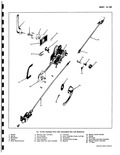
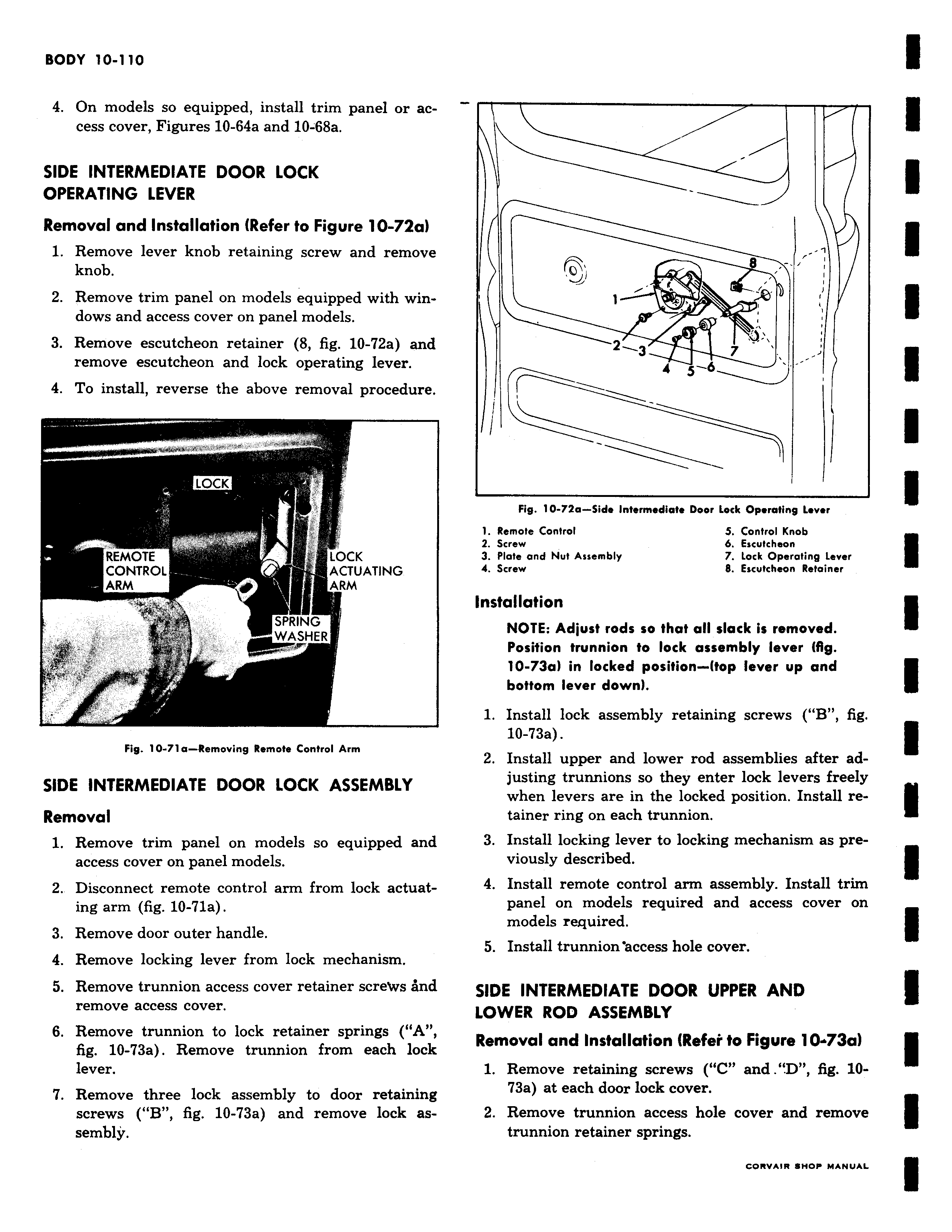
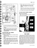
4 On models so equipped install trim panel or access cover Figures 10 64a and 10 68a SIDE INTERMEDIATE DOOR LOCK OPERATING LEVER Removal and Installation Refer to Figure 10 72a 1 Remove lever knob retaining screw and remove knob 2 Remove trim panel on models equipped with windows and access cover on panel models 3 Remove escutcheon retainer 8 fig 10 72a and remove escutcheon and lock operating lever 4 To install reverse the above removal procedure LOCK Y REMOTE LOCK CONTROL ACTUATING ARM ARM SPRING WASHER Fig 10 71 a Removing Remote Control Arm SIDE INTERMEDIATE DOOR LOCK ASSEMBLY Removal 1 Remove trim panel on models so equipped and access cover on panel models 2 Disconnect remote control arm from lock actuating arm fig 10 71a 3 Remove door outer handle 4 Remove locking lever from lock mechanism 5 Remove trunnion access cover retainer screws And remove access cover 6 Remove trunnion to lock retainer springs A fig 10 73a Remove trunnion from each lock lever 7 Remove three lock assembly to door retaining screws B fig 10 73a and remove lock assembly i J t J0 ll rv 2 3 I 4 5 6 7 Fig 10 72a Side intermediate Door Lock Operating Lever 1 Remote Control S Control Knob 2 Screw b Escutcheon 3 Plate and Nut Assembly 7 Lock Operating Lever 4 Screw 8 Escutcheon Retainer Installation NOTE Adjust rods so that all slack is removed Position trunnion to lock assembly lever fig 10 73a in locked position top lever up and bottom lever down 1 Install lock assembly retaining screws B fig 10 73a 2 Install upper and lower rod assemblies after adjusting trunnions so they enter lock levers freely when levers are in the locked position Install retainer ring on each trunnion 3 Install locking lever to locking mechanism as previously described 4 Install remote control arm assembly Install trim panel on models required and access cover on models required 5 Install trunnion access hole cover SIDE INTERMEDIATE DOOR UPPER AND LOWER ROD ASSEMBLY Removal and Installation tRefet to Figure 10 73a1 1 Remove retaining screws C and D fig 1073a at each door lock cover 2 Remove trunnion access hole cover and remove trunnion retainer springs

 Next
Next