Jeep Parts Wiki | Ford Parts Wiki
Home | Search | Browse | Marketplace | Messages | FAQ | Guest
Prev

 Next
Next
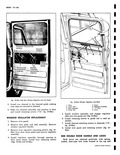
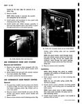
I r 1 2 A 3 v A 4 Fig 10 66a Chann l and Run Assembly 1 Run Assembly 4 Channel Assembly Rear 2 Clip 5 Door Seal 3 Screw 6 Channel Assembly Front bottom of each door The locking mechanisms are con tained entirely within the door structures A measure r of safety in the event of a collision is provided wit interlocks at the top and bottom of the rear side door Both an inside and outside release handle is pro vided for the side intermediate door The inside release handle is identical to that used for the front door fig 10 64a while the outside release fig 10 61a i a 2 position lever type handle In the closed door position the handle is horizontal to open the door the handle is turned downward 45 degrees after the dow is opened the handle automatically moves upward tc the horizontal position setting the lock bolts so the door can be closed A rubber bumper integral with the side intermediate door handle eliminates interference with the body when the door is fully opened anothe rubber bumper on the side rear door outer pane serves the same purpose fig 10 61a The side rear door release handle located on the door inner side face is of the lever type fig 10 56a A separate key lock fig 10 61a below the inter mediate side door handle locks both side doors since the side intermediate door laps over the side rear door Both doors can be locked from the inside with a locking knob the locking knob has a notch on the face of the knob When notch is up door is locked When knob is turned to the left the door is unlocked fig 10 64a located on the inner panel of the front side door Should the doors be locked from the outside they cannot be unlocked from the inside since the inside and outside locks operate independently of each other See Figure 10 70a exploded view of the side intermediate door lock mechanism SIDE INTERMEDIATE DOOR HANDLE Removal and Installation Refer to Figure 10 67a 1 Open doors 2 On panel doors remove lock assembly access cover retainer screws and remove cover fig 10 68a On doors equipped with windows remove trim panel fig 10 64a 3 Remove retainer ring 1 fig 10 67a from escutcheon 3 fig 10 67a Access to retainer ring is through opening in panel door fig 10 69a or through opening when trim panel is removed for doors with windows NOTE Removal of lock assembly is not necessary for handle removal An access hole is 3 7 b I 11 12 9 8 V ly 14 0 Fig 10 67a Side Intermediate Door Handle Assembly 1 Spring Retainer 9 Cement as req d 2 Gasket 10 Lock Cylinder Retainer 3 Escutcheon 11 Lock Cylinder 4 Spring 12 Cover Ring S Lockwasher 13 Cover 6 Screw 14 Screw 7 Handle 15 Reinforcement 8 Rubber Bumper Assembly

 Next
Next