Jeep Parts Wiki | Ford Parts Wiki
Home | Search | Browse
Prev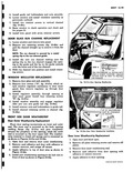
 Next
Next
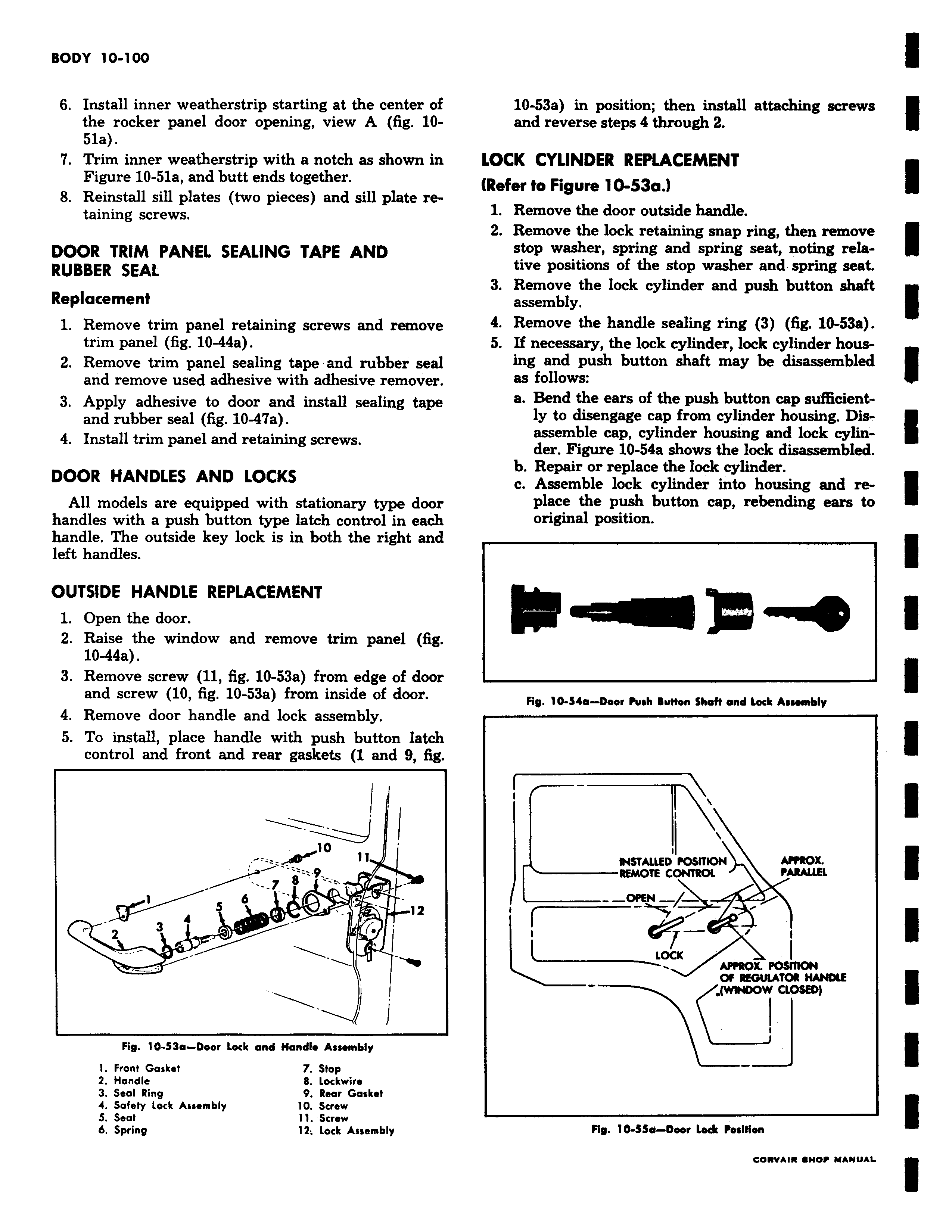
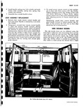
6 Install inner weatherstrip starting at the center of the rocker panel door opening view A fig 1051a 7 Trim inner weatherstrip with a notch as shown in Figure 10 51a and butt ends together 8 Reinstall sill plates two pieces and sill plate retaining screws DOOR TRIM PANEL SEALING TAPE AND RUBBER SEAL Replacement 1 Remove trim panel retaining screws and remove trim panel fig 10 44a 2 Remove trim panel sealing tape and rubber seal and remove used adhesive with adhesive remover 3 Apply adhesive to door and install sealing tape and rubber seal fig 10 47a 4 Install trim panel and retaining screws DOOR HANDLES AND LOCKS All models are equipped with stationary type door handles with a push button type latch control in each handle The outside key lock is in both the right and left handles OUTSIDE HANDLE REPLACEMENT 1 Open the door 2 Raise the window and remove trim panel fig 10 44a 3 Remove screw 11 fig 10 53a from edge of door and screw 10 fig 10 53a from inside of door 4 Remove door handle and lock assembly 5 To install place handle with push button latch control and front and rear gaskets 1 and 9 fig J io m 7 8 f l 6 4 12 3 Jr I Fig 10 53a Door Lock and Handle Assembly 1 Front Gasket 7 Stop 2 Handle 8 Lockwire 3 Seal Ring 9 Rear Gasket 4 Safety Lock Assembly 10 Screw 5 Seat 11 Screw 6 Spring 12 lock Assembly 10 53a in position then install attaching screws and reverse steps 4 through 2 LOCK CYLINDER REPLACEMENT Refer to Figure 10 53a 1 Remove the door outside handle 2 Remove the lock retaining snap ring then remove stop washer spring and spring seat noting relative positions of the stop washer and spring seat 3 Remove the lock cylinder and push button shaft assembly 4 Remove the handle sealing ring 3 fig 10 53a 5 I necessary the lock cylinder lock cylinder housing and push button shaft may be disassembled as follows a Bend the ears of the push button cap sufficiently to disengage cap from cylinder housing Disassemble cap cylinder housing and lock cylinder Figure 10 54a shows the lock disassembled b Repair or replace the lock cylinder c Assemble lock cylinder into housing and replace the push button cap rebending ears to original position Fig 10 54a Door Push luffon Shaft end lock Assembly i INSTALLED POSITION APPROX REMOTE C PARALLEL I 1 LOCK APPROX POSITION OF REGUUTOR HANDLE iwtNDO i QOM Fig 10 55d Deer Lodt Position eewAu ewnw MANUAL