Jeep Parts Wiki | Ford Parts Wiki
Home | Search | Browse
Prev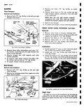
 Next
Next
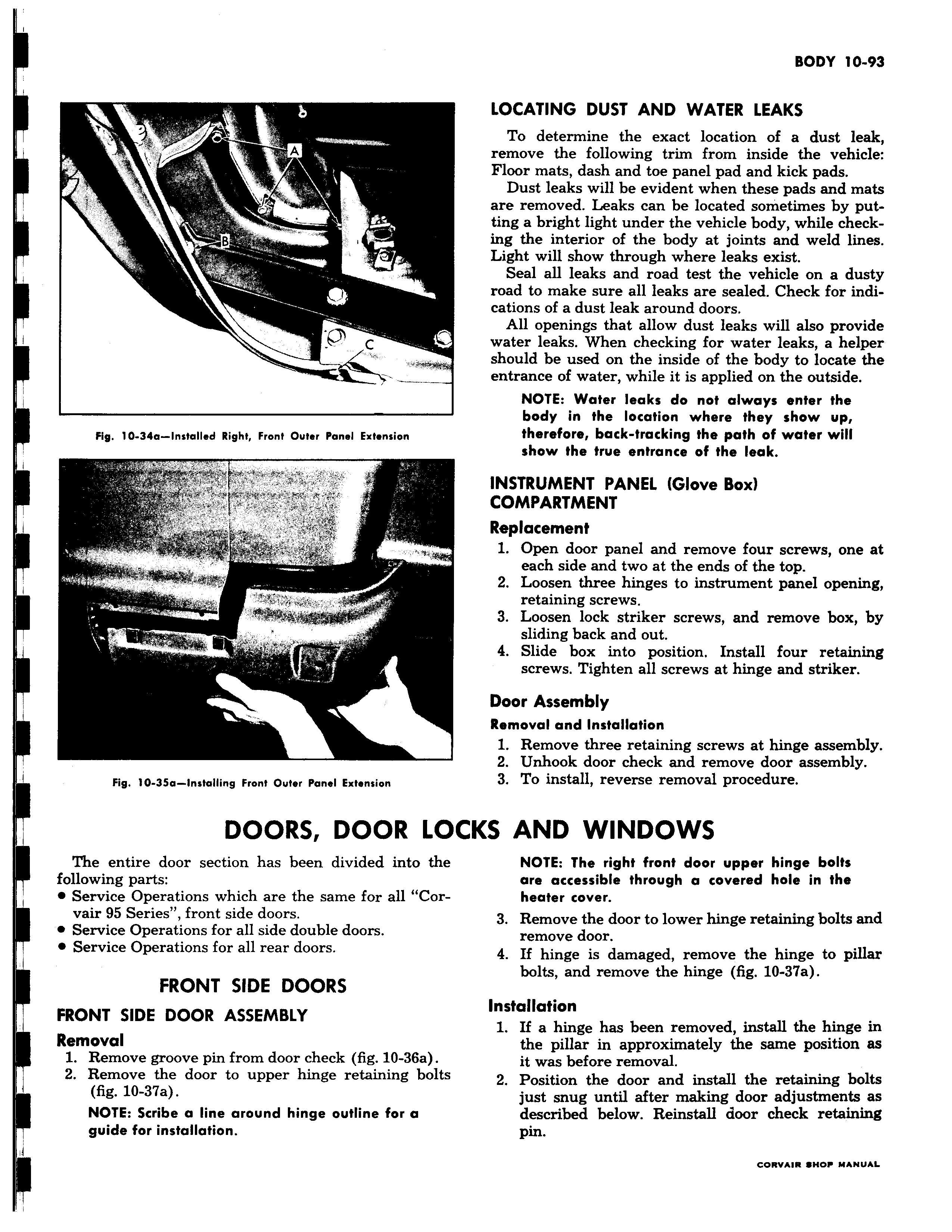
A B 3 C Fig 10 34a Installed Right Front Outer Panel Extension rt w f r a a Fig 10 35a Installing Front Outer Panel Extension DOORS DOOR LO The entire door section has been divided into the following parts Service Operations which are the same for all Corvair 95 Series front side doors 0 Service Operations for all side double doors Service Operations for all rear doors FRONT SIDE DOORS FRONT SIDE DOOR ASSEMBLY Removal 1 Remove groove pin from door check fig 10 36a 2 Remove the door to upper hinge retaining bolts fig 10 37a NOTE Scribe a line around hinge outline for a guide for installation LOCATING DUST AND WATER LEAKS To determine the exact location of a dust leak remove the following trim from inside the vehicle Floor mats dash and toe panel pad and kick pads Dust leaks will be evident when these pads and mats are removed Leaks can be located sometimes by putting a bright light under the vehicle body while checking the interior of the body at joints and weld lines Light will show through where leaks exist Seal all leaks and road test the vehicle on a dusty road to make sure all leaks are sealed Check for indications of a dust leak around doors All openings that allow dust leaks will also provide water leaks When checking for water leaks a helper should be used on the inside of the body to locate the entrance of water while it is applied on the outside NOTE Water leaks do not always enter the body in the location where they show up therefore back tracking the path of water will show the true entrance of the leak INSTRUMENT PANEL Glove Box COMPARTMENT Replacement 1 Open door panel and remove four screws one at each side and two at the ends of the top 2 Loosen three hinges to instrument panel opening retaining screws 3 Loosen lock striker screws and remove box by sliding back and out 4 Slide box into position Install four retaining screws Tighten all screws at hinge and striker Door Assembly Removal and Installation 1 Remove three retaining screws at hinge assembly 2 Unhook door check and remove door assembly 3 To install reverse removal procedure CKS AND WINDOWS NOTE The right front door upper hinge bolts are accessible through a covered hole in the heater cover 3 Remove the door to lower hinge retaining bolts and remove door 4 If hinge is damaged remove the hinge to pillar bolts and remove the hinge fig 10 37a Installation 1 If a hinge has been removed install the hinge in the pillar in approximately the same position as it was before removal 2 Position the door and install the retaining bolts just snug until after making door adjustments as described below Reinstall door check retaining pin