Jeep Parts Wiki | Ford Parts Wiki
Home | Search | Browse | Marketplace | Messages | FAQ | Guest
Prev
 Next
Next
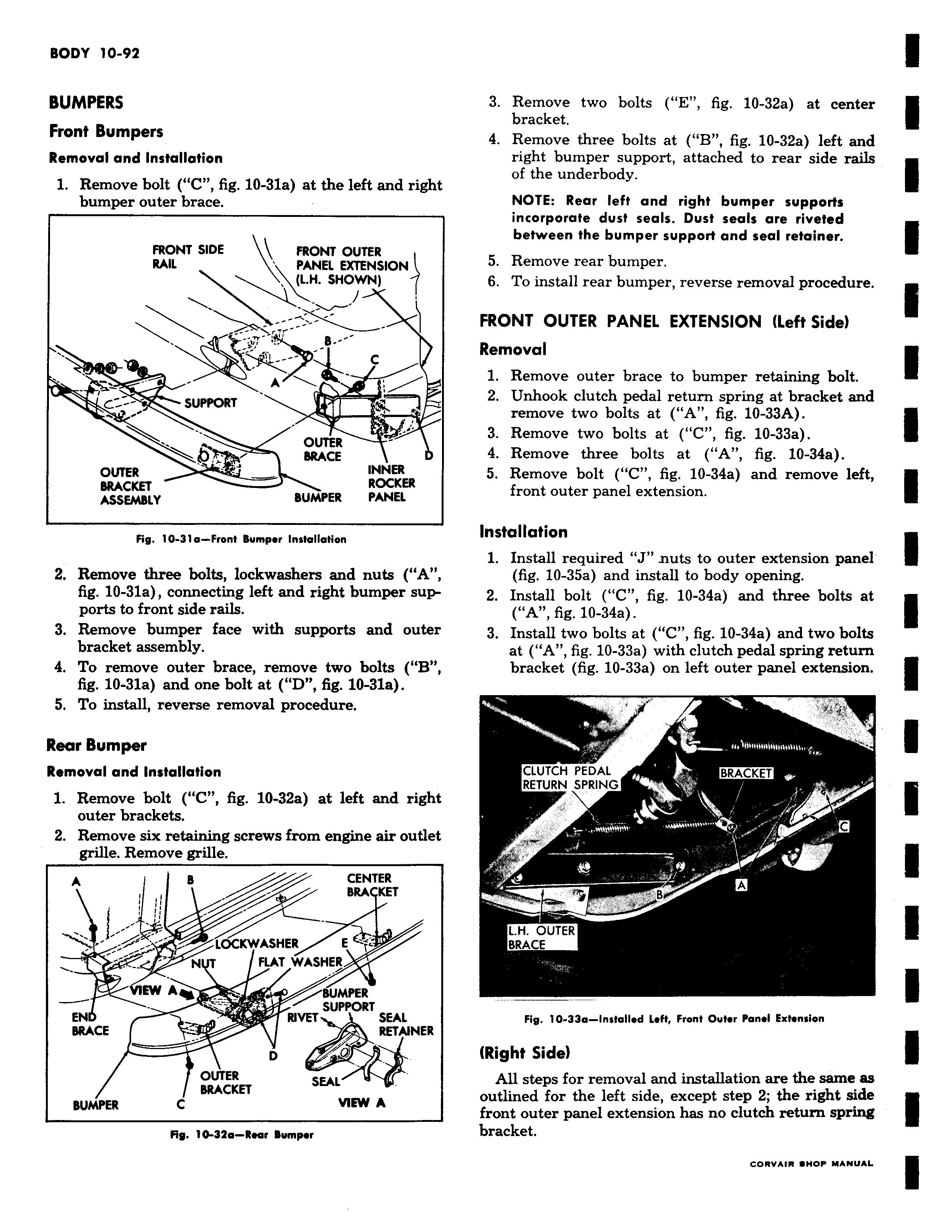
BUMPERS Front Bumpers Removal and Installation 1 Remove bolt C fig 10 31a at the left and right bumper outer brace FRONT SIDE FRONT OUTER RAIL PANEL EXTENSION L H SHOWN C G SUPPORT OUTER BRACE OUTER INNER BRACKET ROCKER ASSEMBLY BUMPER PANEL Fig 10 31a Front Bumper Installation 2 Remove three bolts lockwashers and nuts A fig 10 31a connecting left and right bumper supports to front side rails 3 Remove bumper face with supports and outer bracket assembly 4 To remove outer brace remove two bolts B fig 10 31a and one bolt at D fig 10 31a 5 To install reverse removal procedure Rear Bumper Removal and Installation 1 Remove bolt C fig 10 32a at left and right outer brackets 2 Remove six retaining screws from engine air outlet grille Remove grille A B CENTER BRA KET v LOCKWASHER E N T FLAT WASHER EW A BU SUPPORT EN RIVET SEAL BRACE RETAINER D O t OUTER SEAL BRACKET BUMPER C VIEW A Fig 10 32a Rear Bumper 3 Remove two bolts E fig 10 32a at center bracket 4 Remove three bolts at B fig 10 32a left and right bumper support attached to rear side rails of the underbody NOTE Rear left and right bumper supports incorporate dust seals Dust seals are riveted between the bumper support and seal retainer 5 Remove rear bumper 6 To install rear bumper reverse removal procedure FRONT OUTER PANEL EXTENSION Left Side Removal 1 Remove outer brace to bumper retaining bolt 2 Unhook clutch pedal return spring at bracket and remove two bolts at A fig 10 33A 3 Remove two bolts at C fig 10 33a 4 Remove three bolts at A fig 10 34a 5 Remove bolt C fig 10 34a and remove left front outer panel extension Installation 1 Install required J nuts to outer extension panel fig 10 35a and install to body opening 2 Install bolt C fig 10 34a and three bolts at A fig 10 34a 3 Install two bolts at C fig 10 34a and two bolts at A fig 10 33a with clutch pedal spring return bracket fig 10 33a on left outer panel extension f r a CLUTCH PEDAL BRACKET RETURN SPRING C s B A l H OUTER BRACE Fig 10 33a Installed Left Front Outer Panel Extension Right Side All steps for removal and installation are the same as outlined for the left side except step 2 the right side front outer panel extension has no clutch return spring bracket