Jeep Parts Wiki | Ford Parts Wiki
Home | Search | Browse | Marketplace | Messages | FAQ | Guest
Prev
 Next
Next
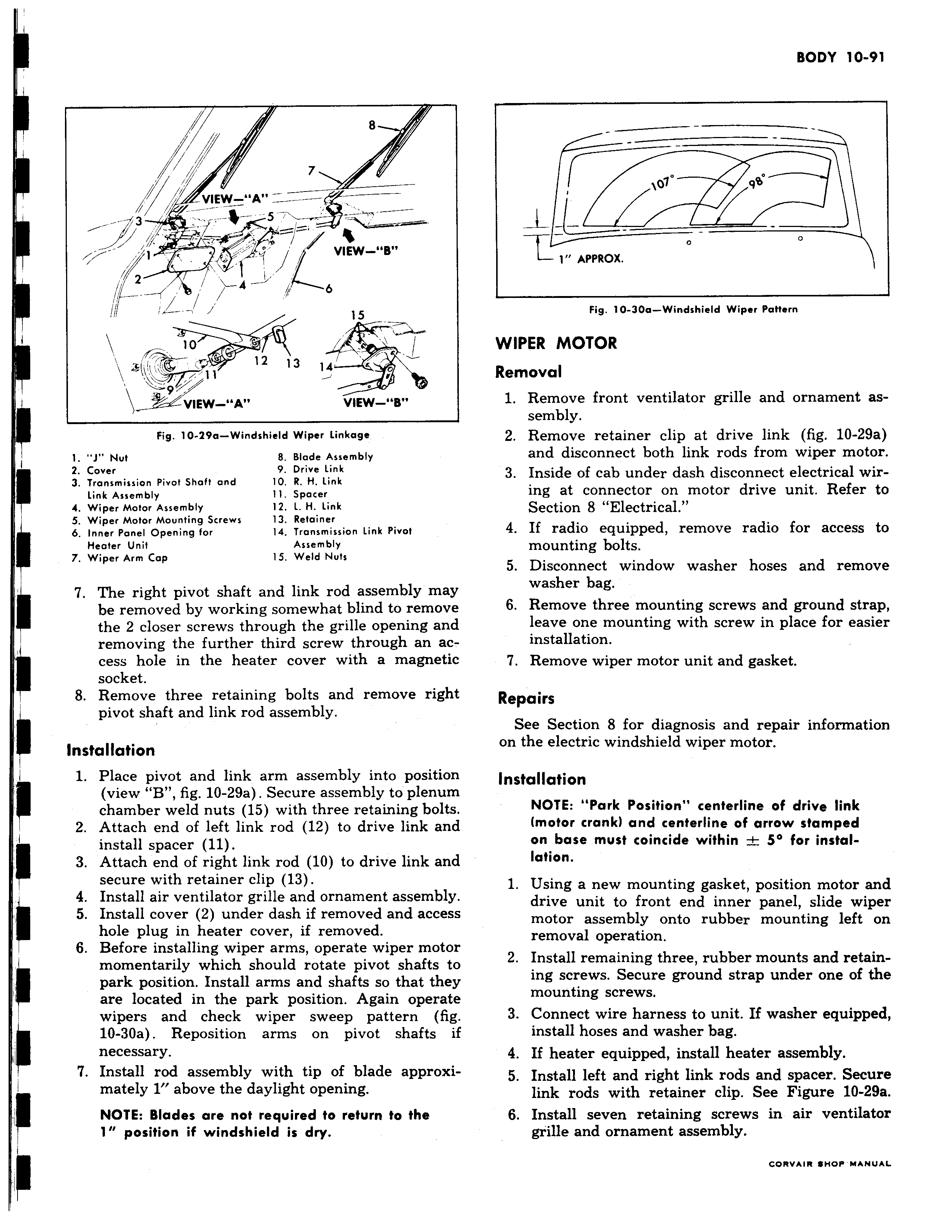
i 7 VIEW A S T s 17F VIEW B I i 4 J i 6 15 10 12 13 la e 9 W A VIEW B Fig 10 49a Windshield Wiper Linkage 1 1 Nut B Blade Assembly 2 Cover 9 Drive link 3 Transmission Pivot Shaft and 10 R H Link Link Assembly 11 Spacer 4 Wiper Motor Assembly 12 l H Link 5 Wiper Motor Mounting Screws 13 Retainer 6 Inner Panel Opening for 14 Transmission Link Pivot Heater Unit Assembly 7 Wiper Arm Cap 15 Weld Nuts 7 The right pivot shaft and link rod assembly mal be removed by working somewhat blind to removi the 2 closer screws through the grille opening an removing the further third screw through an ac cess hole in the heater cover with a magnetii socket 8 Remove three retaining bolts and remove righ pivot shaft and link rod assembly Installation I 1 Place pivot and link arm assembly into positiol view B fig 10 29a Secure assembly to plenun chamber weld nuts 15 with three retaining bolt 2 Attach end of left link rod 12 to drive link ani install spacer 11 3 Attach end of right link rod 10 to drive link ani secure with retainer clip 13 4 Install air ventilator grille and ornament assembl3 5 Install cover 2 under dash if removed and acces hole plug in heater cover if removed 6 Before installing wiper arms operate wiper moto momentarily which should rotate pivot shafts t park position Install arms and shafts so that the are located in the park position Again operat wipers and check wiper sweep pattern fil 10 30a Reposition arms on pivot shafts i necessary 7 Install rod assembly with tip of blade approxi mately 1 above the daylight opening NOTE Blades are not required to return to the 1 position if windshield is dry 010 99 1 APPROX Fig 10 30a Windshield Wiper Pattern WIPER MOTOR Removal 1 Remove front ventilator grille and ornament assembly 2 Remove retainer clip at drive link fig 10 29a and disconnect both link rods from wiper motor 3 Inside of cab under dash disconnect electrical wiring at connector on motor drive unit Refer to Section 8 Electrical 4 If radio equipped remove radio for access to mounting bolts 5 Disconnect window washer hoses and remove r washer bag 6 Remove three mounting screws and ground strap 1 leave one mounting with screw in place for easier installation 7 Remove wiper motor unit and gasket Repairs See Section 8 for diagnosis and repair information on the electric windshield wiper motor Installation i NOTE Park Position centerline of drive link motor crank and centerline of arrow stamped on base must coincide within 5 for instal1 lation 1 Using a new mounting gasket position motor and drive unit to front end inner panel slide wiper motor assembly onto rubber mounting left on removal operation r 2 Install remaining three rubber mounts and retaining screws Secure ground strap under one of the mounting screws 3 Connect wire harness to unit If washer equipped install hoses and washer bag 4 If heater equipped install heater assembly 5 Install left and right link rods and spacer Secure link rods with retainer clip See Figure 10 29a 6 Install seven retaining screws in air ventilator grille and ornament assembly