Jeep Parts Wiki | Ford Parts Wiki
Home | Search | Browse | Marketplace | Messages | FAQ | Guest
Prev
 Next
Next
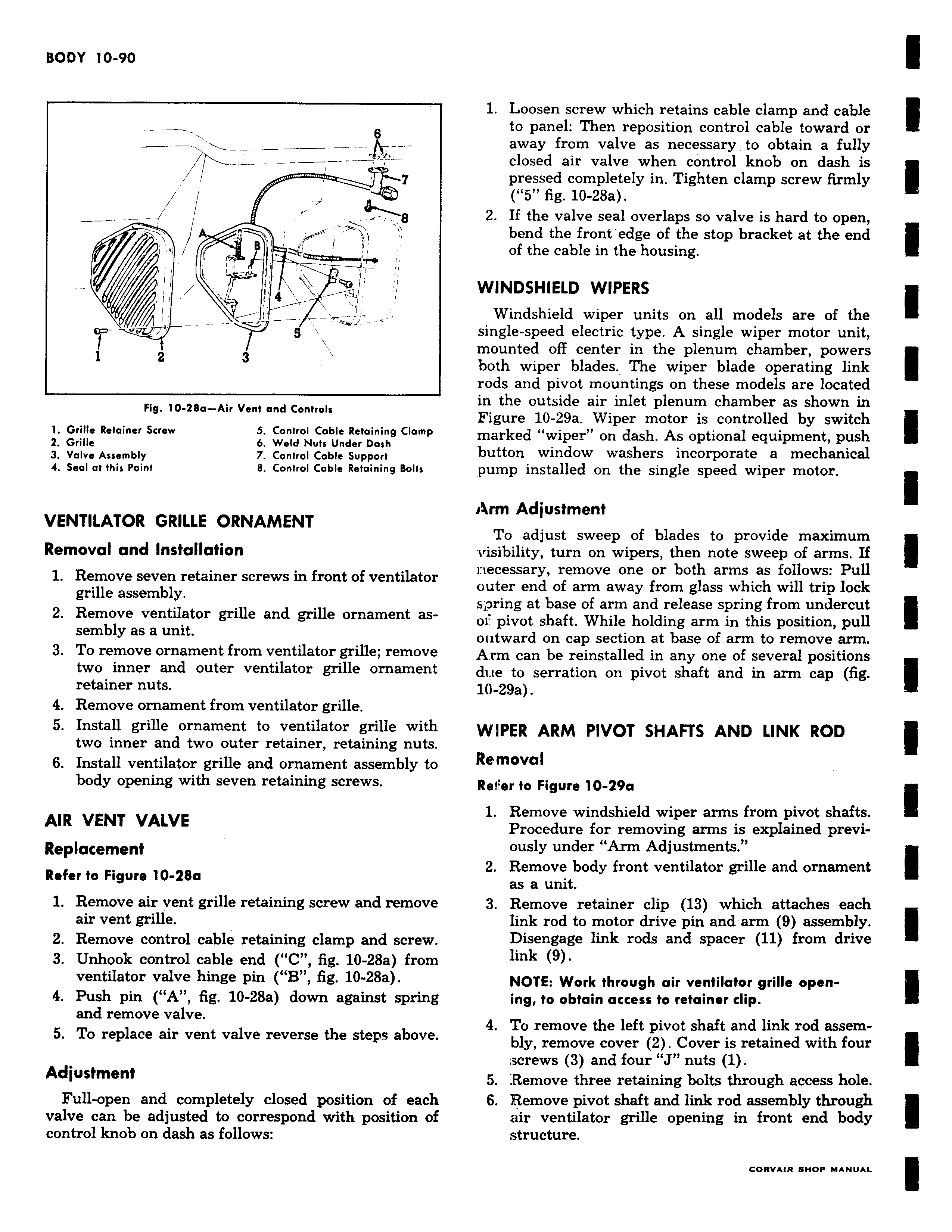
w r 8 v 4 l g v 1 2 Fig 10 28a Air Vent and Controls l Grille Retainer Screw 5 Control Cable Retaining Clamp 2 Grille 6 Weld Nuts Under Dash 3 Valve Assembly 7 Control Cable Support 4 Seal at this Point 8 Control Cable Retaining Bolts VENTILATOR GRILLE ORNAMENT Removal and Installation 1 Remove seven retainer screws in front of ventilator grille assembly 2 Remove ventilator grille and grille ornament assembly as a unit 3 To remove ornament from ventilator grille remove two inner and outer ventilator grille ornament retainer nuts 4 Remove ornament from ventilator grille 5 Install grille ornament to ventilator grille with two inner and two outer retainer retaining nuts 6 Install ventilator grille and ornament assembly to body opening with seven retaining screws AIR VENT VALVE Replacement Refer to Figure 10 28a 1 Remove air vent grille retaining screw and remove air vent grille 2 Remove control cable retaining clamp and screw 3 Unhook control cable end C fig 10 28a from ventilator valve hinge pin B fig 10 28a 4 Push pin A fig 10 28a down against spring and remove valve 5 To replace air vent valve reverse the steps above Adjustment Full open and completely closed position of each valve can be adjusted to correspond with position of control knob on dash as follows 1 Loosen screw which retains cable clamp and cable to panel Then reposition control cable toward or away from valve as necessary to obtain a fully closed air valve when control knob on dash is pressed completely in Tighten clamp screw firmly 5 fig 10 28a 2 If the valve seal overlaps so valve is hard to open bend the front edge of the stop bracket at the end of the cable in the housing WINDSHIELD WIPERS Windshield wiper units on all models are of the single speed electric type A single wiper motor unit mounted off center in the plenum chamber powers both wiper blades The wiper blade operating link rods and pivot mountings on these models are located in the outside air inlet plenum chamber as shown in Figure 10 29a Wiper motor is controlled by switch marked wiper on dash As optional equipment push button window washers incorporate a mechanical pump installed on the single speed wiper motor Arm Adjustment To adjust sweep of blades to provide maximum visibility turn on wipers then note sweep of arms If rtecessary remove one or both arms as follows Pull outer end of arm away from glass which will trip lock spring at base of arm and release spring from undercut o pivot shaft While holding arm in this position pull outward on cap section at base of arm to remove arm Arm can be reinstalled in any one of several positions due to serration on pivot shaft and in arm cap fig 10 29a WIPER ARM PIVOT SHAFTS AND LINK ROD Removal Ref er to Figure 10 29a 1 Remove windshield wiper arms from pivot shafts Procedure for removing arms is explained previously under Arm Adjustments 2 Remove body front ventilator grille and ornament as a unit 3 Remove retainer clip 13 which attaches each link rod to motor drive pin and arm 9 assembly Disengage link rods and spacer 11 from drive link 9 NOTE Work through air ventilator grille opening to obtain access to retainer dip 4 To remove the left pivot shaft and link rod assembly remove cover 2 Cover is retained with four screws 3 and four J nuts 1 5 Remove three retaining bolts through access hole 6 Remove pivot shaft and link rod assembly through air ventilator grille opening in front end body structure