Jeep Parts Wiki | Ford Parts Wiki
Home | Search | Browse
Prev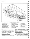
 Next
Next
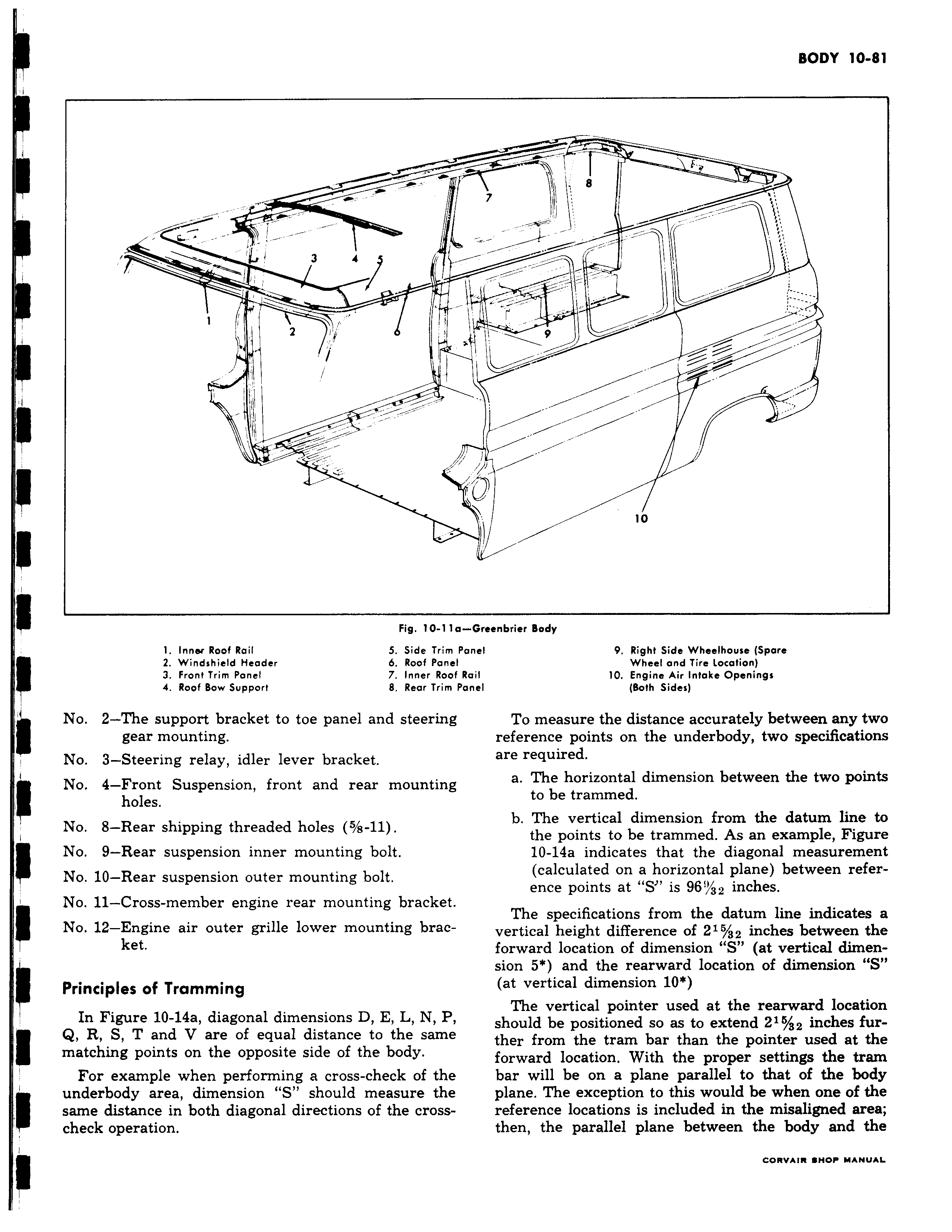
a 3 4 S i Fig 10 11 1 Inner Roof Rail 5 Side Trim 2 Windshield Header 6 Roof Pane 3 Front Trim Panel 7 Inner Roo 4 Roof Bow Support 8 Rear Trim I No 2 The support bracket to toe panel and steerin gear mounting No 3 Steering relay idler lever bracket No 4 Front Suspension front and rear mountinj holes No 8 Rear shipping threaded holes 5 s 11 t No 9 Rear suspension inner mounting bolt No 10 Rear suspension outer mounting bolt No 11 Cross member engine rear mounting bracket No 12 Engine air outer grille lower mounting bracket Principles of Tramming In Figure 10 14a diagonal dimensions D E L N P Q R S T and V are of equal distance to the same matching points on the opposite side of the body For example when performing a cross check of the underbody area dimension S should measure the same distance in both diagonal directions of the crosscheck operation r 1I e 7 v i i 0 a Greenbrier Body Panel 9 Right Side Wheelhouse Spare I Wheel and Tire location f Rail 10 Engine Air Intake Openings Panel Both Sides To measure the distance accurately between any two reference points on the underbody two specifications are required a The horizontal dimension between the two points to be trammed b The vertical dimension from the datum line to the points to be trammed As an example Figure 10 14a indicates that the diagonal measurement calculated on a horizontal plane between reference points at S is 96 32 inches The specifications from the datum line indicates a vertical height difference of 215 32 inches between the forward location of dimension S at vertical dimension 5 and the rearward location of dimension S at vertical dimension 10 The vertical pointer used at the rearward location should be positioned so as to extend 216 a2 inches further from the tram bar than the pointer used at the forward location With the proper settings the tram bar will be on a plane parallel to that of the body plane The exception to this would be when one of the reference locations is included in the misaligned area then the parallel plane between the body and the cnevm woo u AE