Jeep Parts Wiki | Ford Parts Wiki
Home | Search | Browse
Prev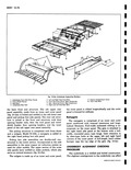
 Next
Next
i i i w I W 3 f D D Fig 10 9a U 1 Dropped Floor Panel 4 Rear Fronl 2 Front Underbody Floor Panel 5 Engine Ca 3 Left Rear Side Rail 6 Engine Fr1 door opening fits Most important however underbody misalignment can influence the suspension system thereby causing many of the problems that arise from a suspension misalignment It is essential therefore that underbody alignment be exact to within t1 16 of the specified dimensions In the event of collision damage it is important that underbody alignment be thoroughly checked and if necessary realigned in order to accurately establish suspension steering and engine mounting locations f There are many classifications of tools that may be employed to correct the average collision damage situation including frame straightening machines lighter external pulling equipment and standard body jacks Frame tools are not considered as essential equipment for average Corvair 95 Series collision repair operations however there will be many situations with this unitized type of construction as with othez types of frame construction where frame equipmenl will be required There are also areas of repair where r even though not essential frame equipment may prove beneficial r W t0 o I v derbody Floor Panels Floor Panel 7 Rear Upper Cross Member mportment Floor Panel 8 Rear Lower Cross Member nt Upper Shield Assembly To assist in checking alignment of the underbody components repairing minor underbody damage or locating replacement parts the following underbody dimension and alignment checking information is presented Body Tram Gage An accurate method of determining the alignment of measuring tram gage The gage required tram perform recommended measuring checks properly must be capable of extending a length of 98 inches At least one of the vertical pointers must be capable of a minimum reach of 17 inches Dimensions A through Z fig 10 14a are calculated on a horizontal plane therefore to make precise measurements sufficient vertical reach is necessary at each end of the tram gage to allow the tram bar to remain on a horizontal plane parallel to the underbody plane during all operations proper r tramming tool is meastiring