Jeep Parts Wiki | Ford Parts Wiki
Home | Search | Browse
Prev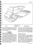
 Next
Next
3 d i w fig 10 6a Front End 1 Instrument Panel S Front Doer Hinge P 2 Windshield Header Inner Panel 6 Body Front Outer N 3 Windshield Header Outer Panel 7 Body Front Outer Pt 4 Front Door Hinge Pillar Outer Panel 8 Body Front Center I When the two underbody sub assemblies are joined the straight floor panel of the rear underbody becomes the dropped center of the underbody assembly fig 10 10a Panels forming the underbody area incorporate attachment provisions for the power train and the suspension system Principal supporting members of the underbody assembly are two full length side rails shown in Figure 10 10a The front underbody side rails are further inboard of the rocker panels than those of the rear underbody Fig 10 10a which provide clearance for the front suspension assembly Smaller rear suspension control arm inclination angles eliminate the offset used at the front The front and rear portions of the side rails use box section construction while the central portions are of C channel section See Figures 10 8a 10 9a and 10 10a JI I a a a a r a 1 1 i i a W 1