Jeep Parts Wiki | Ford Parts Wiki
Home | Search | Browse
Prev
 Next
Next
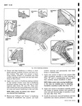
4 Insert a strong cord into pinchweld cavity of rubber channel tie ends together at bottom center and tape to inside surface of glass 5 Apply a continuous ribbon of medium bodied sealet to rubber channel as shown at 3 in Sectior B B Figure 10 95 completely around channel 6 With the aid of a helper position back window assembly into body opening and align center marks While helper is applying hand pressure to outside surface of glass carefully pull ends of cord acros bottom up sides and across top of window openin to seat lip of rubber channel over pinchweld flangE completely around perimeter of back window NOTE On 527 models check outer lip of rubber channel to make sure lip is seating properly completely around the opening 7 On 727 models install back window revea mouldings as described under BACK WINDOVf REVEAL MOULDINGS 727 Model 8 Using a pressure type applicator apply weather strip adhesive black between rubber channel anc glass on inside and outside of glass as indicated a 4 in Section B B Figure 10 95 around entin perimeter of glass 9 Clean off excess sealer and cement Install bacl window garnish mouldings and remove protectiv4 coverings HEADLINING The headlining assembly is formed to contour by con cealed listing wires The ends of each listing wire an installed into holes in listing wire clips secured to th side roof rails The wire and listing pocket at the cente roof bow are secured to the side roof rails The wire ano listing pocket at the center roof bow are secured to thi bow by bend over metal tabs The rear listing wire i secured at the center of the back window inner panel b3 a bend over tab The headlining is secured at the wind shield quarter windows and back window by cemen and tacks or staples At the door openings the head lining is cemented around the flange of the roof inne rail In addition a rear quarter filler upper foundatioi assembly is located at each rear quarter pillar Th4 assembly is secured in place by cement and by tacks o staples at the quarter window area NOTE Clean hands are essential when working with headlining material Removal 1 Place protective coverings over seat cushions an backs 2 Prior to removing headlining remove followin hardware and trim items a Rear view mirror support b Sunshade support assembly c Windshield upper garnish mouldings d Back window upper garnish mouldings e Rear quarter window upper garnish mouldings f Dome lamp g Pinchweld finishing strip along top of each door opening sufficiently to expose edge of headlining 3 On each side of body lower rear quarter window and remove tacks securing forward edge of rear quarter filler upper foundation assembly See View H Figure 10 96 Then turn back trim and with a suitable flat bladed tool carefully break cement bond between foundation assembly and pillar and remove assembly 4 Carefully detach cemented edge of headlining l frome side roof rail at each door opening See View F 5 Carefully remove tacks or staples securing headlining at windshield quarter window and back window openings then carefully detach cemented edges of headlining 6 Working from front to rear of body disengage headlining listing wires from side roof rails gathering or rolling headlining with listing wires on out side to keep headlining clean At center roof bow bend down metal tabs shown in View E securing listing wire and at center of back window bend down tab securing center of rear listing wire See View G Remove headlining a 7 If necessary listing wires may be removed from pockets r 1 Installation 1 If previously removed install listing wires into headlining listing pockets and lift entire assembly into body NOTE Make certain paper covered wire is in stalled in center listing wire pocket 2 Install rear listing wire Center and align rear of headlining in relation to back window and rear quarter windows then bend over tab securing center of rear listing wire See View G Then working forward install ends of listing wires into listing wire holes in side roof rails NOTE Make certain ends of listing wires are installed in correct holes to insure proper contour of headlining IS View F 1 3 At center roof bow check headlining for proper centering and bend tabs over listing wire See View E Install remaining listing wires into holes in side roof rails