Jeep Parts Wiki | Ford Parts Wiki
Home | Search | Browse | Marketplace | Messages | FAQ | Guest
Prev
 Next
Next
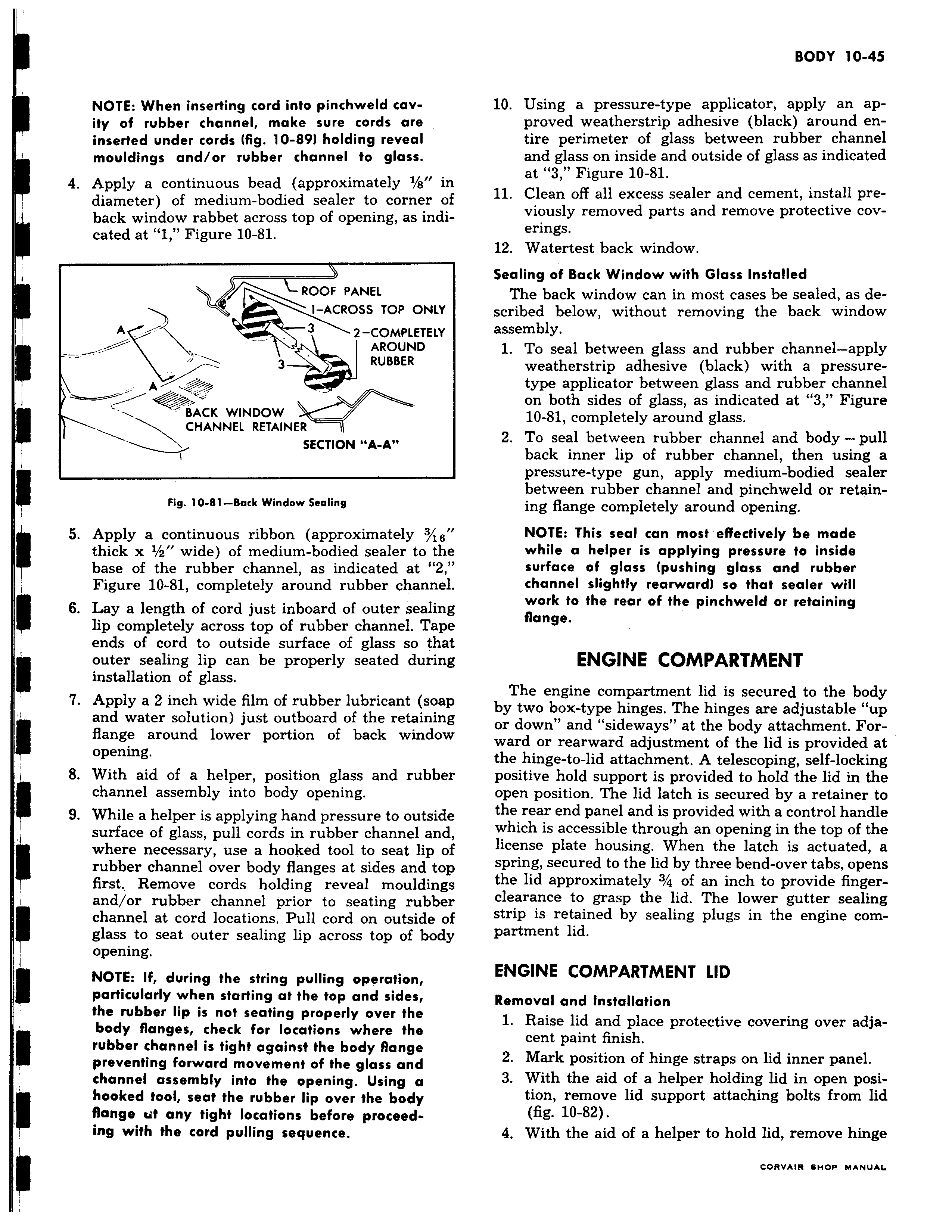
NOTE When inserting cord into pinchweld cavity of rubber channel make sure cords are inserted under cords fig 10 89 holding reveal mouldings and or rubber channel to glass 4 Apply a continuous bead approximately 1 s in diameter of medium bodied sealer to corner of back window rabbet across top of opening as indicated at 1 Figure 10 81 ROOF PANEL 1 ACROSS TOP ONLY A 3 2 COMPLETELY AROUND 3 RUBBER A BACK WINDOW CHANNEL RETAINER I y SECTION A A Fig 10 81 Back Window Sealing 5 Apply a continuous ribbon approximately 3 s thick x i a wide of medium bodied sealer to the base of the rubber channel as indicated at 2 Figure 10 81 completely around rubber channel 6 Lay a length of cord just inboard of outer sealing lip completely across top of rubber channel Tape ends of cord to outside surface of glass so that outer sealing lip can be properly seated during installation of glass 7 Apply a 2 inch wide film of rubber lubricant soap and water solution just outboard of the retaining flange around lower portion of back window opening 8 With aid of a helper position glass and rubber channel assembly into body opening 9 While a helper is applying hand pressure to outside surface of glass pull cords in rubber channel and where necessary use a hooked tool to seat lip of rubber channel over body flanges at sides and top first Remove cords holding reveal mouldings and or rubber channel prior to seating rubber channel at cord locations Pull cord on outside of glass to seat outer sealing lip across top of body opening NOTE If during the string pulling operation particularly when starting at the top and sides the rubber lip is not seating properly over the body flanges check for locations where the rubber channel is tight against the body flange preventing forward movement of the glass and channel assembly into the opening Using a hooked tool seat the rubber lip over the body flange ut any tight locations before proceeding with the cord pulling sequence 10 Using a pressure type applicator apply an approved weatherstrip adhesive black around entire perimeter of glass between rubber channel and glass on inside and outside of glass as indicated at 3 Figure 10 81 11 Clean off all excess sealer and cement install previously removed parts and remove protective coverings 12 Watertest back window Sealing of Back Window with Glass Installed The back window can in most cases be sealed as described below without removing the back window assembly 1 To seal between glass and rubber channel apply weatherstrip adhesive black with a pressuretype applicator between glass and rubber channel on both sides of glass as indicated at 3 Figure 10 81 completely around glass 2 To seal between rubber channel and body pull back inner lip of rubber channel then using a pressure type gun apply medium bodied sealer between rubber channel and pinchweld or retaining flange completely around opening NOTE This seal can most effectively be made while a helper is applying pressure to inside surface of glass pushing glass and rubber channel slightly rearward so that sealer will work to the rear of the pinchweld or retaining flange ENGINE COMPARTMENT The engine compartment lid is secured to the body by two box type hinges The hinges are adjustable up or down and sideways at the body attachment Forward or rearward adjustment of the lid is provided at the hinge to lid attachment A telescoping self locking positive hold support is provided to hold the lid in the open position The lid latch is secured by a retainer to the rear end panel and is provided with a control handle which is accessible through an opening in the top of the license plate housing When the latch is actuated a spring secured to the lid by three bend over tabs opens the lid approximately 3 4 of an inch to provide fingerclearance to grasp the lid The lower gutter sealing strip is retained by sealing plugs in the engine compartment lid ENGINE COMPARTMENT LID Removal and Installation 1 Raise lid and place protective covering over adjacent paint finish 2 Mark position of hinge straps on lid inner panel 3 With the aid of a helper holding lid in open position remove lid support attaching bolts from lid fig 10 82 4 With the aid of a helper to hold lid remove hinge